Connection example with a safety control relay – Rockwell Automation 2727-G7P20D1Q7 MobileView Guard G750 Quick Start User Manual
Page 9
MobileView Guard G750 9
Publication 2727-QS002E-MU-P
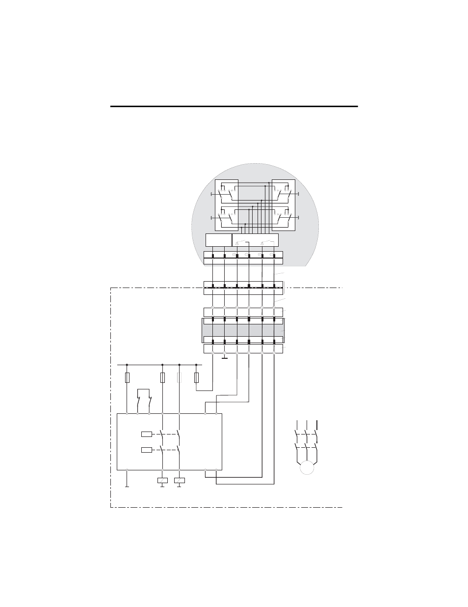
Connection Example with a Safety Control Relay
The diagram below shows suggested wiring for enabling switches using an
PILZ PST safety control relay to meet safety category 3. Refer to PILZ PST
documentation for additional information.
P IL Z
P S T 1
GND
A1 (+)
2 3
S 1 1
A2 (-)
1 3
1 4
2 4
S 2 3
S 2 4
K A
K B
S 1 2
K 1
K 2
+2 4 V D C
F 1
1 A
F 2
4 A(t)
or
6 A(f)
K A
K B
X 1
X 2
K A
K B
L 1
L 2
L 3
M
F 3
4 A(t)
or
6 A(f)
GND
GND
F 4
3 ,1 5 A
GND
1
2
3
4
1
2
3
4
1 2 3
1 2 3
3 2 1
3 2 1
1 2 3
1 2 3
3 2 1
3 2 1
Z T 1
L
Z T 2
L
Z T 1
R
Z T 2
R
D C /D C
converter
6
7
6
7
S 1 9 :
K 3 :
7
8
1 2
1 7
K 1 :
1
2
K 1 :
7
8
1 2
1 7
1
2
+2 4 V
GND
E D 1 +
E D 1 -
E D 2 +
E D 2 -
X 1
X 2
+2 4 V
GND
E D 1 +
E D 1 -
E D 2 +
E D 2 -
K 4 :
K 3 :
E valuation electronics
C ircuit 1
C ircuit 2
Z T x
y
....... enabling switch x
y
F eedback
control loop
C ontrol cabinet
Connection cable
MobileView
17-pin coinvers jack
Intermediate cable
MobileView
Terminal block socket K3
on connection box
Male connector X1 on
connection box
Connection box
Male connector X2 on
connection box
Terminal block socket K4 on
connection box
Enabling of
dangerous
movement
Note: All contacts of KA and KB must be force-guided!
MobileView
(2 enabling switches with 3
positions and 2 circuits each)