Replacing sharing resistors, Uniform clamping pressure – Rockwell Automation 7000A PowerFlex Medium Voltage AC Drive (A Frame) - ForGe Control User Manual
Page 82
82
Rockwell Automation Publication 7000A-UM200C-EN-P - June 2014
Chapter 3
Component Definition and Maintenance
Replacing Sharing Resistors
Normally the sharing resistor is part of the snubber resistor assembly.
Replacement of the sharing resistor also requires replacing the snubber resistor.
The sharing and snubber resistors are normally located on the backside of the
PowerCage. See
Replacing Snubber and Sharing Resistor
Uniform Clamping Pressure
Always maintain proper pressure on the thyristors. Follow this procedure
whenever changing devices or loosening the clamp completely.
1.
Apply a thin layer of Electrical Joint Compound (Alcoa EJC No. 2 or
approved equivalent) to the clamp head pressure pad face (
).
Apply the compound using a small brush, and gently wipe the pad face
with an industrial wipe until a thin film remains. Ensure no brush bristles
remain.
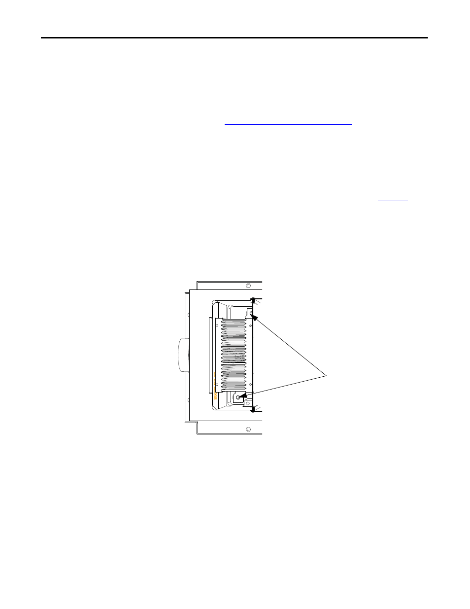
2.
Torque the heat sink bolts to 13.5 N•m (10 lb•ft.), then loosen each bolt
two complete turns.
Figure 70 - Location of Heat sink bolts
3.
Tighten the clamp to the proper force until you can turn the indicating
washers by the fingers with some resistance.
4.
Torque the heat sink bolts to 13.5 N•m (10 lb•ft.) starting with the center
heat sink and moving outward alternating left to right.
5.
Check the clamp indicating washer.
Heat sink bolt location