Rockwell Automation 7000A PowerFlex Medium Voltage AC Drive (A Frame) - ForGe Control User Manual
Page 39
Rockwell Automation Publication 7000A-UM200C-EN-P - June 2014
39
Drive Installation
Chapter 2
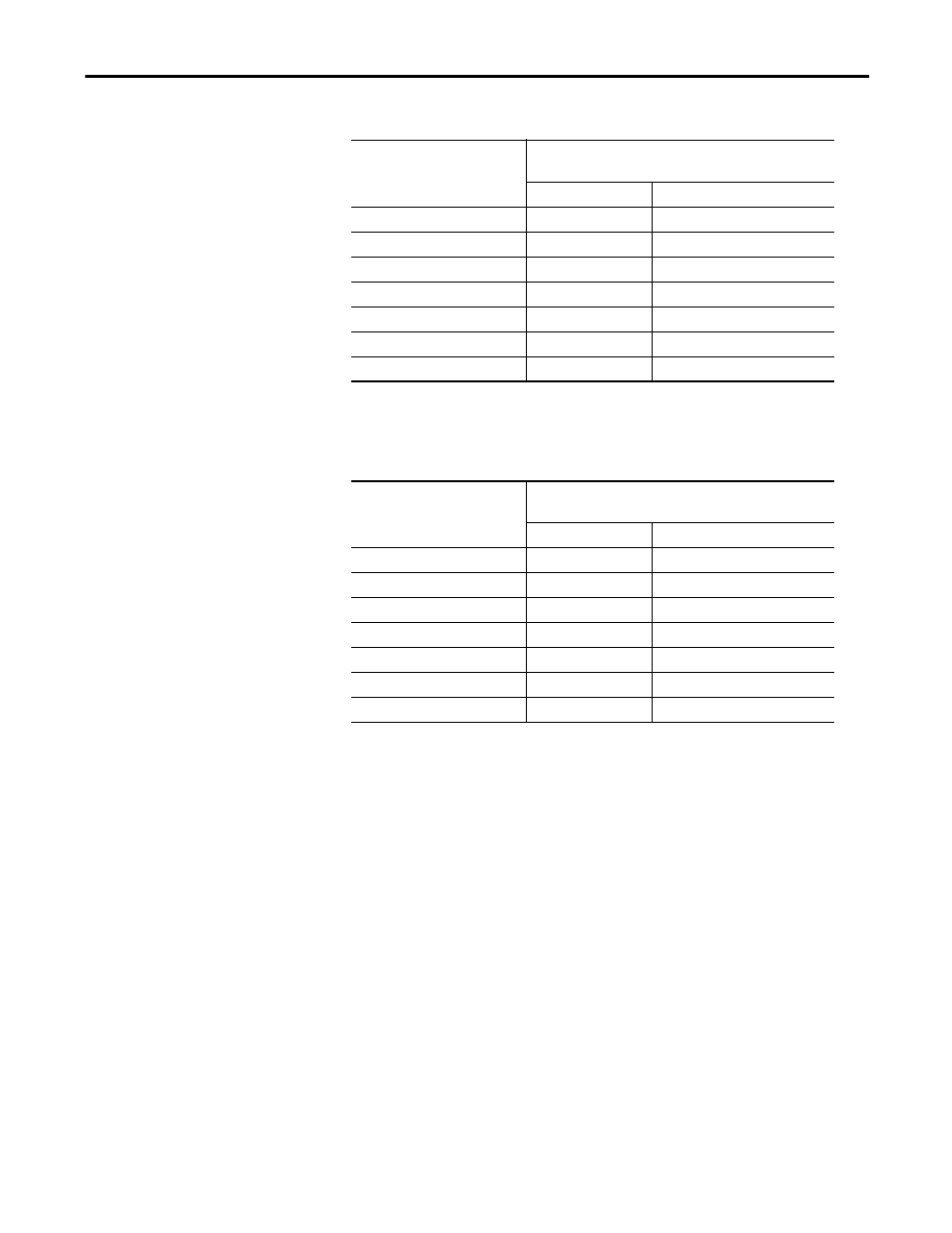
Cable Insulation Requirements for AFE Drives with Separate Isolation Transformer
Cable Insulation Requirements for “Direct-to-Drive” Technology or Integral Isolation
Transformer
The following table identifies general wire categories that will be encountered
when installing the PowerFlex 7000 “A” Frame Drive. Each category has an
associated wire group number that is used in the following sections to identify the
wire to be used. Application and signal examples along with the recommended
type of cable for each group are provided. A matrix providing the recommended
minimum spacing between different wire groups run in the same tray or separate
conduit is also provided.
System Voltage (V, RMS)
Cable Insulation Rating (kV)
(Maximum Peak Line-to-Ground)
(1)
(1) Cabling from secondary side of Isolation Transformer to input of VFD
Machine Side
2400
4.1
2.2
3000
5.12
2.75
3300
5.63
3.0
4160
7.1
3.8
6000
10.8
5.5
6300
11.4
5.8
6600
11.8
6.0
System Voltage (V, RMS)
Cable Insulation Rating (kV)
(Maximum Peak Line-to-Ground)
Line Side
Machine Side
2400
2.2
2.2
3000
2.75
2.75
3300
3.0
3.0
4160
3.8
3.8
6000
5.5
5.5
6300
5.8
5.8
6600
6.0
6.0