Output calibration, Power supply replacement – Rockwell Automation 7000A PowerFlex Medium Voltage AC Drive (A Frame) - ForGe Control User Manual
Page 122
122
Rockwell Automation Publication 7000A-UM200C-EN-P - June 2014
Chapter 3
Component Definition and Maintenance
Output Calibration
Ensure the output of the supply is 56V DC.
There is a potentiometer on the top of the power supply that adjusts the 56 V DC
output for the power supply. Isolate the output of the power supplies; multiple
supplies in series will affect your measurements. With the control power on and the
output of the AC/DC Converter isolated from the drive control, adjust the
potentiometer until the output equals 56V DC. Perform this test on each power
supply. When all adjustments are complete, re-connect the power supply to the
circuit and re-measure the output. Readjust if necessary.
If it is not possible to maintain 56V DC, the power supply may be faulty.
Power Supply Replacement
1.
Ensure control power has been isolated and locked out.
2.
Disconnect the terminals at the unit.
3.
Remove the four M6 bolts per
4.
Extract the power supply complete with bracket from the drive.
5.
Remove the bracket(s) from the failed power supply (four M4 screws and
nylon shoulder washers).
6.
Attach bracket to replacement power supply. The Black Insulation(s) must
be between the AC/DC power supply and the mounting plate(s).
7.
Repeat Steps 5 through 1 in this order to replace the unit (
or
).
8.
Reapply control power and verify voltage levels.
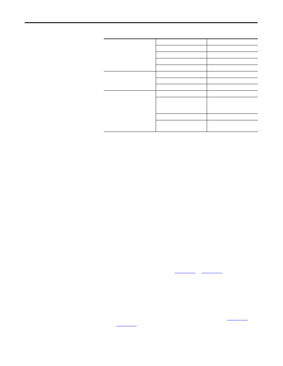
P1-AC Input
PIN#
LABEL
AC (L)
Live
AC (N)
Neutral
NC
No Connection
FG
Earth
P2-DC Output
PIN#
LABEL
+
+56V
–
+56V COMM
P3-Fail Output
PIN#
LABEL
CN1
1-2 Connected
3-4 Connected
5, 6, 7, 8, 9, 10 N/C
CN2
N/C
CN3
7 - Alarm
8 - Alarm GND