Rockwell Automation 7000A PowerFlex Medium Voltage AC Drive (A Frame) - ForGe Control User Manual
Page 71
Rockwell Automation Publication 7000A-UM200C-EN-P - June 2014
71
Component Definition and Maintenance
Chapter 3
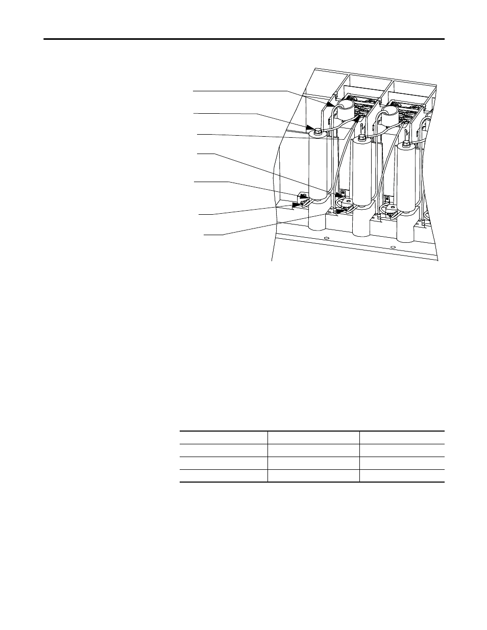
Figure 56 - Snubber Circuit Assembly for SGCT module
In addition to the snubber circuit, a sharing resistor is connected in parallel with
the SGCT. The function of the sharing resistor is to ensure the voltage is shared
equally among the SGCTs when connected in series. SGCTs are connected in
series to increase the total reverse voltage blocking (PIV) capacity as seen by the
electrical circuit. A single SGCT has a PIV rating of 6500V. This single device
will provide sufficient design margin for electrical systems with 2400V medium
voltage supply. At 4160V, two SGCTs must be connected in series to provide a
net PIV of 13,000V to achieve the necessary design margin. Similarly, three
SGCTs must be connected in series at 6600V, providing a net PIV of 19,500V to
achieve the necessary design margin.
The cooling requirements of the SGCT are achieved by placing the SGCT
between two forced air-cooled heatsinks, one heatsink on the anode and the
other heatsink on the cathode. The clamp assembly on the right hand side of the
inverter module generates these forces.
Pressure on the SGCTs must be uniform to prevent damage and to ensure low
thermal resistance. Uniform pressure can be achieved by loosening the heatsink
mounting bolts, tightening the clamp and then tightening the heatsink bolts.
External filtered air will be directed through the slots of the heatsinks to carry
away the generated heat from the SGCTs. The door filter is necessary to ensure
the slots on the heatsinks do not get plugged with dust particles.
Cs-1
Rsh
Rsn-2
Rsn-1
Anode
Cs-2
Cathode
SGCT
Device Diameter
Clamp Force
400 A SGCT
38 mm
8.6 kN
800 A SGCT
47 mm
13.5 kN
1500 A SGCT
63 mm
20 kN