Converter cabinet, Voltage-sensing assembly – Rockwell Automation 7000A PowerFlex Medium Voltage AC Drive (A Frame) - ForGe Control User Manual
Page 60
60
Rockwell Automation Publication 7000A-UM200C-EN-P - June 2014
Chapter 3
Component Definition and Maintenance
Converter Cabinet
The converter cabinet contains three rectifier modules and three inverter
modules.
shows a 3300/4160V converter with a PWM Rectifier.
Isolated Gate Driver Power Supplies (IGDPS) are mounted on the cabinet’s right
side sheet (6600V, 2400V Drives) and on the cabinet’s left side sheet (3300V,
4160V Drives).
Thermal sensors are installed on the top module of the inverter and rectifier. The
exact location depends on the drive configuration.
Voltage-Sensing Assembly
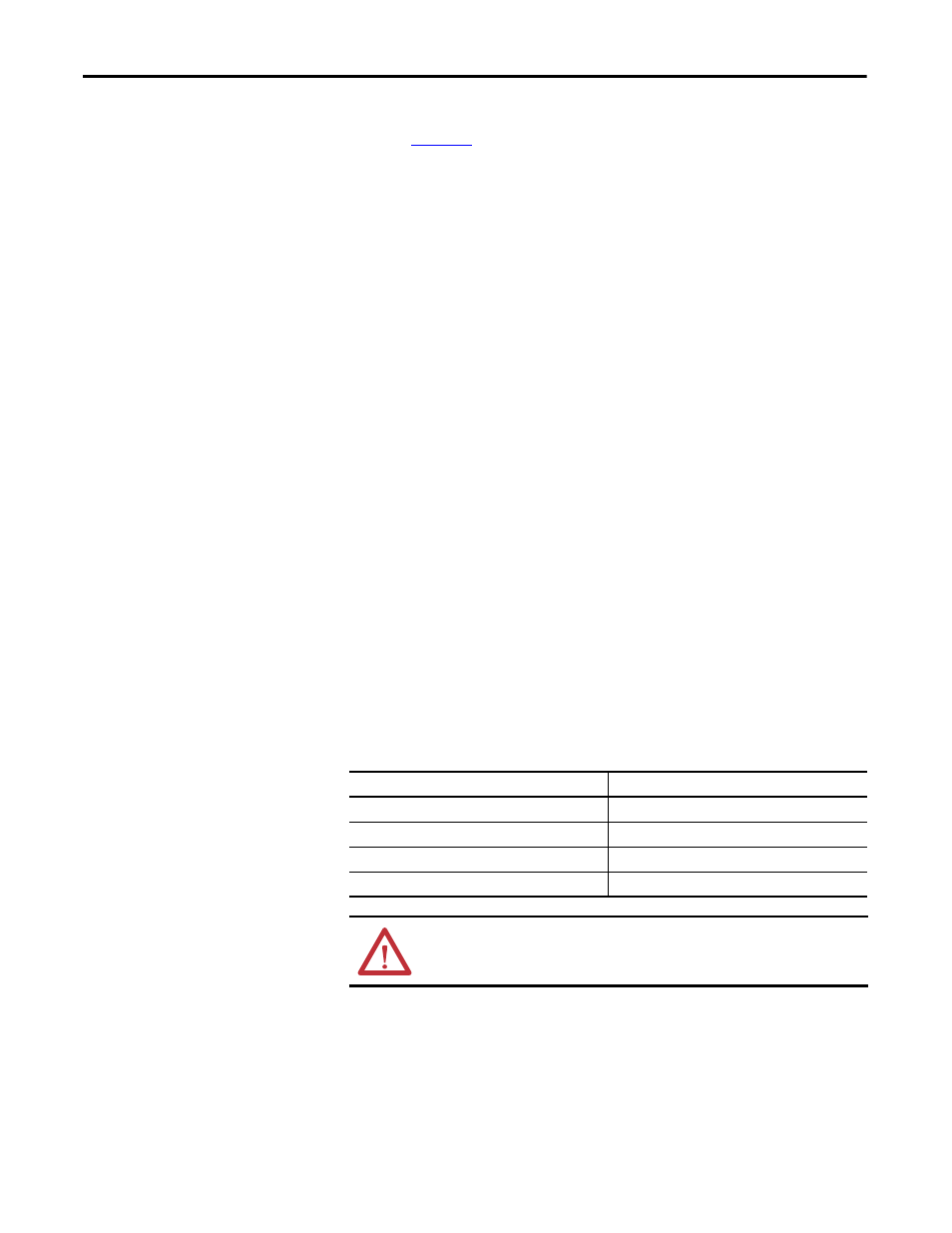
Below is a table of the input voltage ranges for each of the input terminals on the
voltage-sensing board. There are four separate inputs taps for each of the six
independent channels. This assembly has been designed to operate at a nominal
input voltage of up to 7200V with a continuous 40% overvoltage. The output
voltages are scaled to provide close to 10V peak for a 140% input voltage at the
high end of each of the voltage ranges.
Each of the channels has only four taps, thus they must be used to provide a range
of input voltages and software will be used to provide a given amount of gain so
that 140% will correspond to the maximum numerical value of the analogue to
digital converter.
Table 2 - Input Voltage Range
Tap
Voltage Range
D
800...1449V
C
1450...2499V
B
2500...4799V
A
4800...7200V
ATTENTION: Grounds must be reconnected on the voltage sensing boards.
Failure to do so may result in injury, death or damage to equipment.