Rockwell Automation 7000A PowerFlex Medium Voltage AC Drive (A Frame) - ForGe Control User Manual
Page 103
Rockwell Automation Publication 7000A-UM200C-EN-P - June 2014
103
Component Definition and Maintenance
Chapter 3
3.
Swing the low voltage panel to the left and disassemble the closing barriers
located on the left and right-hand side of the panel by removing the nuts
and washers which secure them to the sides of the structure.
In some instances, depending on the size of the DC link, it may be
necessary to completely remove the low voltage panel from the drive
cabinet. This can be accomplished by lifting the panel off its hinges and
shifting or rotating it to a position where it does not obstruct the opening
to the DC link cabinet. Ensure that equipment used to lift and support
the panel during DC link replacement is adequate for this purpose.
4.
Disconnect the four power connections. The DC link is equipped with
flexible power leads.
5.
Disconnect wires at terminal block on DC link for thermal switch.
6.
Remove the hardware that secures the DC link.
7.
Disconnect the ground connection.
The DC link is heavy and has provision for lifting with forks of a lift truck.
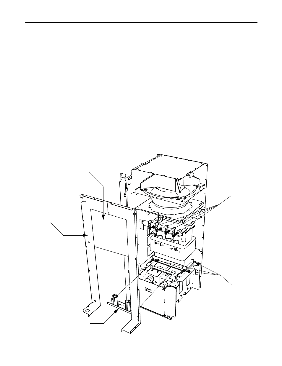
Figure 85 - DC link removal
Fan Barrier
Step 3: Unfasten DC Link leads
and remove terminal assembly.
Disconnect ground wire and LV
wires for thermal switch
Step 4: Remove DC Link
hardware and lift link out
of the front of the drive
Step 2: Remove grounding
filter/network assembly
Step 1: Remove hardware
and DC Link and fan barrier