Enter or modify dfa instruction information – Rockwell Automation D64046.5.1 U MNL WIN DDMC User Manual
Page 81
Chapter 5
Configuring DFA Instructions
5-7
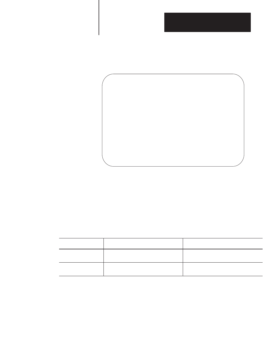
The system displays the DFA instruction (see the figure below).
DFA Instruction
| +DFA–––––––––––––––––––––––––+ |
+––––––––––––––––––––––––––––––––––––––––––+DIAGNOSTIC FAULT ANNUNCIATOR+–(EN)–+
| |Control File | |
| |No. of I/O +–(ER)–|
| |Program File No. | |
| +––––––––––––––––––––––––––––+ |
| |
+––––––––––––––––––––––––––––––––[END OF FILE]–––––––––––––––––––––––––––––––––+
| |
Enter the operand.
Enter the Control File address>
Program Forces:Disabled Edits:None PLC–5/25 Addr 5
Enter or Modify DFA Instruction Information
Once the DFA instruction is displayed, the system prompts you to enter the
Control File Starting Address. To enter parameters into the DFA
instruction:
1.
Type the Control File address and press
[ENTER].
The control file must be expressed in the following manner:
For the:
Use this format:
Where:
PLC-5
Nfff:eee
fff = an integer file between 10 - 999 and
eee = an element number between 0 - 999.
PLC-5/250
Nffff:eeee
ffff = an integer file between 10 - 9999 and
eeee = an element number between 0 - 9999.
In the PLC-5/250, when you enter the control file address, the system
displays a number (1, 2, 3, or 4) in front of the address. This number
represents the logic processor in the PLC-5/250.
The PLC-5/250 chassis supports up to four logic processor modules.
For more information on logic processors, refer to the PLC-5/250
Programming Software Documentation Set (publication 9313-5250).