Rockwell Automation D64046.5.1 U MNL WIN DDMC User Manual
Page 38
Configuring SDS Instructions
Chapter 4
4-2
The SmartDirected Sequencer (SDS) instruction resides in ladder logic and
provides state control that can be used to characterize normal and abnormal
conditions.
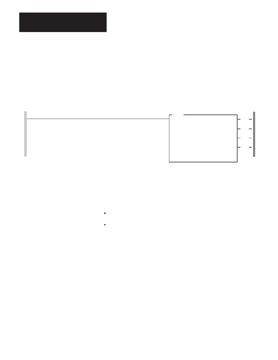
The figure below shows an SDS instruction in a ladder program.
An SDS Instruction Ladder Program
SDS
SMART DIRECTED SEQUENCER
Control File
Step Desc. File
Length
No. of Steps
Position/Step:
No. of I/O
Prog file number
(EN)
(ST)
(ER)
N10:0
N11:0
144
12
0
8
3
DRILL
MACHINE
HEAD 1
(ES)
The SDS instruction permits the user to classify groups of input values into
equation form. When an equation is physically satisfied by input conditions,
the SDS transitions to the destination step appropriate to that equation and
applies the output control related to that step.
The SDS instruction allows two basic types of logic equations:
transitional
combinatorial
Transitional Equations
The SDS instruction which uses transition equations provides traditional
state-based control. Essentially, this type of SDS instruction is built around the
state transition concept, where each input transition directs the instruction to a
unique next step using a logical OR structure. In other words, one input change
directs the instruction to step A, another to step B, etc. See the next page for an
example of what is meant by transitional equations.
Smart Directed Sequencer
Overview