Rockwell Automation D64046.5.1 U MNL WIN DDMC User Manual
Page 15
Chapter 1
Understanding How a DDMC32 System Works
1-3
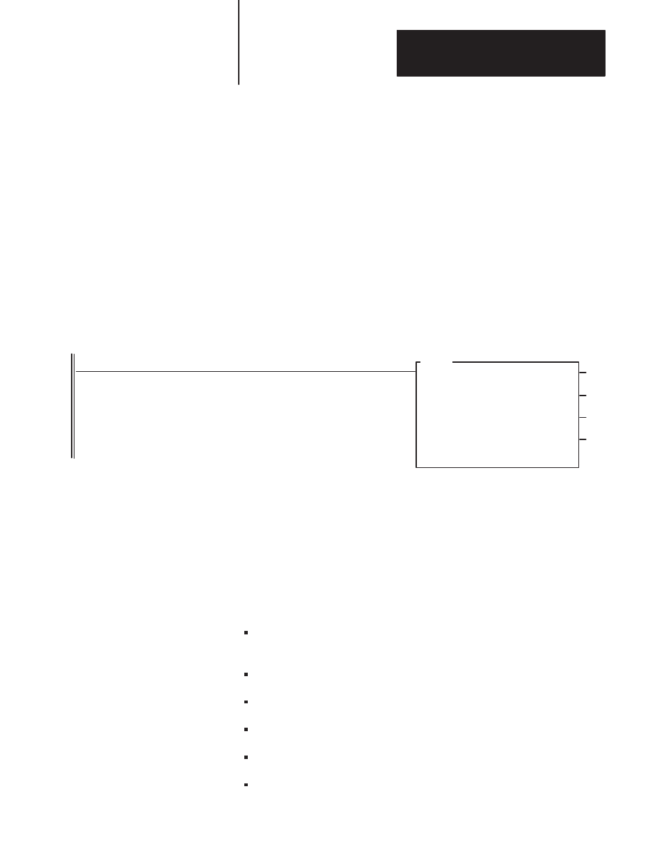
An integral part of the DDMC32 system is the Smart Directed Sequencer
(SDS) instruction (see the figure below). The SDS instruction provides
state-based control and resides in ladder logic. The SDS instruction lets
you develop control and diagnostic programs using state logic. The SDS
instruction is provided as a custom application routine (CAR) which is
downloadable into the PLC-5 processor through 6200 Series software prior
to instruction entry. The CAR occupies one program file and is declared
when entering an SDS instruction; it is referenced by the SDS instruction
at runtime.
Smart Directed Sequencer Instruction Terminal Display (PLC-5
processor)
SDS
SMART DIRECTED SEQUENCER
Control File
Step Desc. File
Length
No. of Steps
Position/Step:
No. of I/O
Prog file number
(EN)
(ST)
(ER)
N10:0
N11:0
144
12
0
8
3
DRILL
MACHINE
HEAD 1
(ES)
Each SDS instruction contains a sequence of user-defined steps which
guide the logical flow of the instruction, for example, Ready, Advancing,
Advanced, etc. Each step represents a unique collection of I/O
(input/output) and subsequent step conditions (or destination steps you
define according to your application). Information for each step is easily
configured through a fill-in-the-blanks configuration template (see next
page). This template contains fields for the following:
inputs and outputs (you enter actual names for control items rather than
obscure addresses)
transitions of the inputs or equations for combined inputs
destination
steps
output
states
step timer (how long until a timeout occurs)
message on or off
Understanding the SDS
Instruction