Rockwell Automation 1785-ENET USER MANUAL PLC-5 ETHERNET INTERFACE User Manual
Page 29
1785-6.5.19 November 1998
Configuring the Interface Module for Ethernet Communication
3-5
2. Make one copy of the Ethernet device template for every PLC-5
Ethernet Interface Module in your system (i.e. one line
per module).
3. Edit each copy of the template as follows:
A. Replace
sidecar
with the name you assigned the Ethernet
interface module. Use only letters and numbers; do not use
underscores.
B.Replace
aa.bb.cc.dd
with the IP address to be assigned to the
interface module.
C.Replace
xxyy
with the last four digits of the Ethernet hardware
address. Use only valid hexadecimal digits (0–9, A–F); do not
use the hyphens or colons that separate the numbers. (You will
find the hardware address on a label affixed to the printed
circuit board of the Ethernet interface module.)
4. Save, close, and make a backup copy of this file.
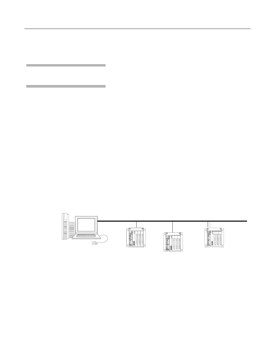
Example
In this example there are three PLC-5 processors (two enhanced
processors and one Ethernet processor) with attached 1785–ENET
interface modules and an HP 9000 workstation. The names and
hardware addresses are device specific:
The term “sidecar” in this template is a logical
name used for identification in this file only. It is not
associated with the stored processor name.
Device
Name
IP Address
Hardware Address
PLC-5/20S
device1
12.34.56.1
00:00:BC:03:12:34
PLC-5/20S
device2
12.34.56.2
00:00:BC:03:56:78
PLC-5/40E
device3
12.34.56.3
00:00:BC:1C:90:12
PLC-5/40S
device4
12.34.56.4
00:00:BC:03:88:27
HP 9000
(HP-UNIX)
computer)
802.3/Ethernet (TCP/IP)
PLC-5/20S
(enhanced PLC-5
processor with
1785-ENET
)
device1
PLC-5/40E with attached
1785-ENET module
(for use of additional
communication port)
devices 3 and 4
PLC-5/20S
(enhanced PLC-5
processor with
1785-ENET
)
device2
BOOTP
server