Rockwell Automation 1791ES-IB16 Guard I/O EtherNet/IP Safety Modules User Manual
Page 64
64
Rockwell Automation Publication 1791ES-UM001D-EN-P - May 2013
Chapter 5
Configure the I/O Modules by Using the Logix Designer Application
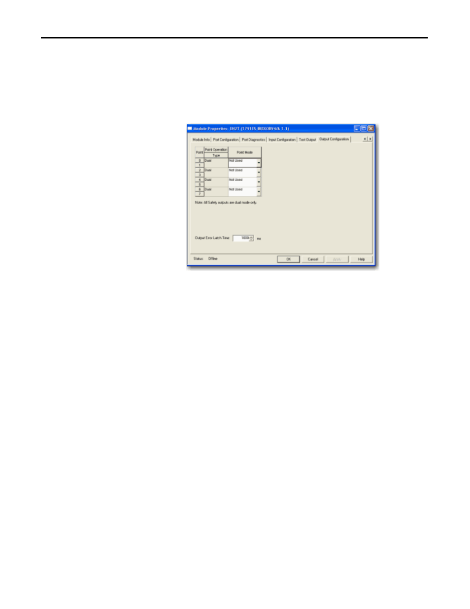
Follow this procedure to complete entries from the Output Configuration dialog
box.
1. For Point Operation, all safety outputs are Dual mode only.
• The Guard I/O module always sets them high or low as a pair.
• You must always match the two outputs as a pair in software as well.
2. For Point Mode, select Not Used, Safety, or Safety Pulse Test, referring to
the Safety Output Parameters table for additional information.
3. Select a value for Output Error Latch Time. Output Error Latch Time is
the time the module holds an error to make sure the controller can detect
it. This provides you more reliable diagnostics and enhances the changes
that a nuisance error is detected.
4. Click Apply from the bottom of the dialog box.