Calibrating your module – Rockwell Automation 1771-N SERIES High Resolution Analog Module User Manual User Manual
Page 70
6–2
Module Calibration
Publication 1771ĆUM127B-EN-P - December 2002
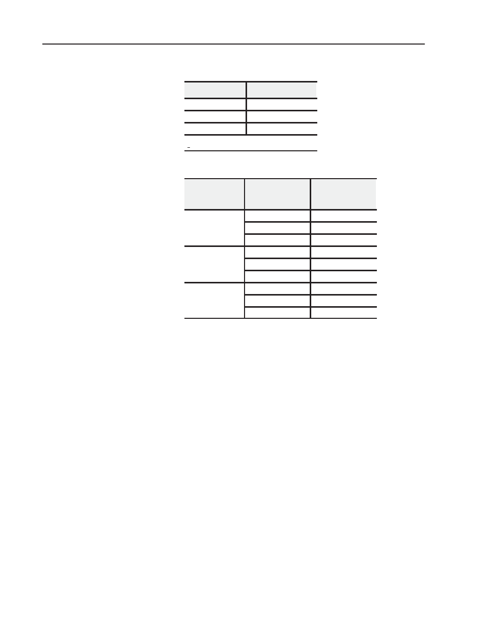
Table 6.A
Resistor Tolerance vs. Expected Error
Resistor Tolerance
Expected Error
0.1%
0.1%
0.5%
0.5%
1.0%
1.0%
Note: If the tolerance error of the 649 ohm resistor is > than
+18 ohms (2.8%), calibration will fail.
Table 6.B
Temperature Coefficient Error
Temperature
Coefficient of
Resistor
nT (Calibration
temperature
deviation from 25
o
C)
Expected Error
5
o
C
0.081 ohms (0.012%)
25ppm/
o
C
10
o
C
0.162 ohms (0.025%)
20
o
C
0.325 ohms (0.05%)
5
o
C
0.162 ohms (0.025%)
50ppm/
o
C
10
o
C
0.325 ohms (0.05%)
20
o
C
0.649 ohms (0.1%)
5
o
C
0.649 ohms (0.1%)
200ppm/
o
C
10
o
C
1.298 ohms (0.2%)
20
o
C
2.596 ohms (0.4%)
Example: Using a 649 ohm resistor, rated for 1% accuracy, with a
temperature coefficient of 50ppm/
o
C, provides an expected accuracy
of 1.05% (1.0% plus 0.05%) when calibration is done at 35
o
C (
nT
of 10
o
C).
The analog module is shipped
already calibrated. If it becomes
necessary to recalibrate the module, you must calibrate the module in
an I/O chassis. The module must communicate with the processor
and an industrial terminal.
Calibration service is available from Allen–Bradley. Contact your
local sales office or field support center for information on how to
send your module in for calibration. Modules under warranty will be
calibrated at no charge. Modules out of warranty, sent in for
calibration only, will be calibrated for less than the standard repair
charge.
Before calibrating the module, you must enter ladder logic into the
processor memory, so that you can send block transfer data to the
module, and the processor can read block transfer data from the
module.
Calibration can be accomplished using any of three methods:
Calibrating Your Module