Sample ladder diagram ć plcć3 familyprocessors – Rockwell Automation 1771-N SERIES High Resolution Analog Module User Manual User Manual
Page 37
3–5
Communicating With Your Analog Module
Publication 1771ĆUM127B-EN-P - December 2002
The differences between the types of 1771-N series modules is
related to the number of output channels each module has. A module
with only inputs (no outputs) requires one BTW after powerup.
Thereafter, it sends back input data and module status by way of
BTRs.
A module with outputs requires BTWs to configure it and update its
output data. BTRs are required to send back input data and module
status.
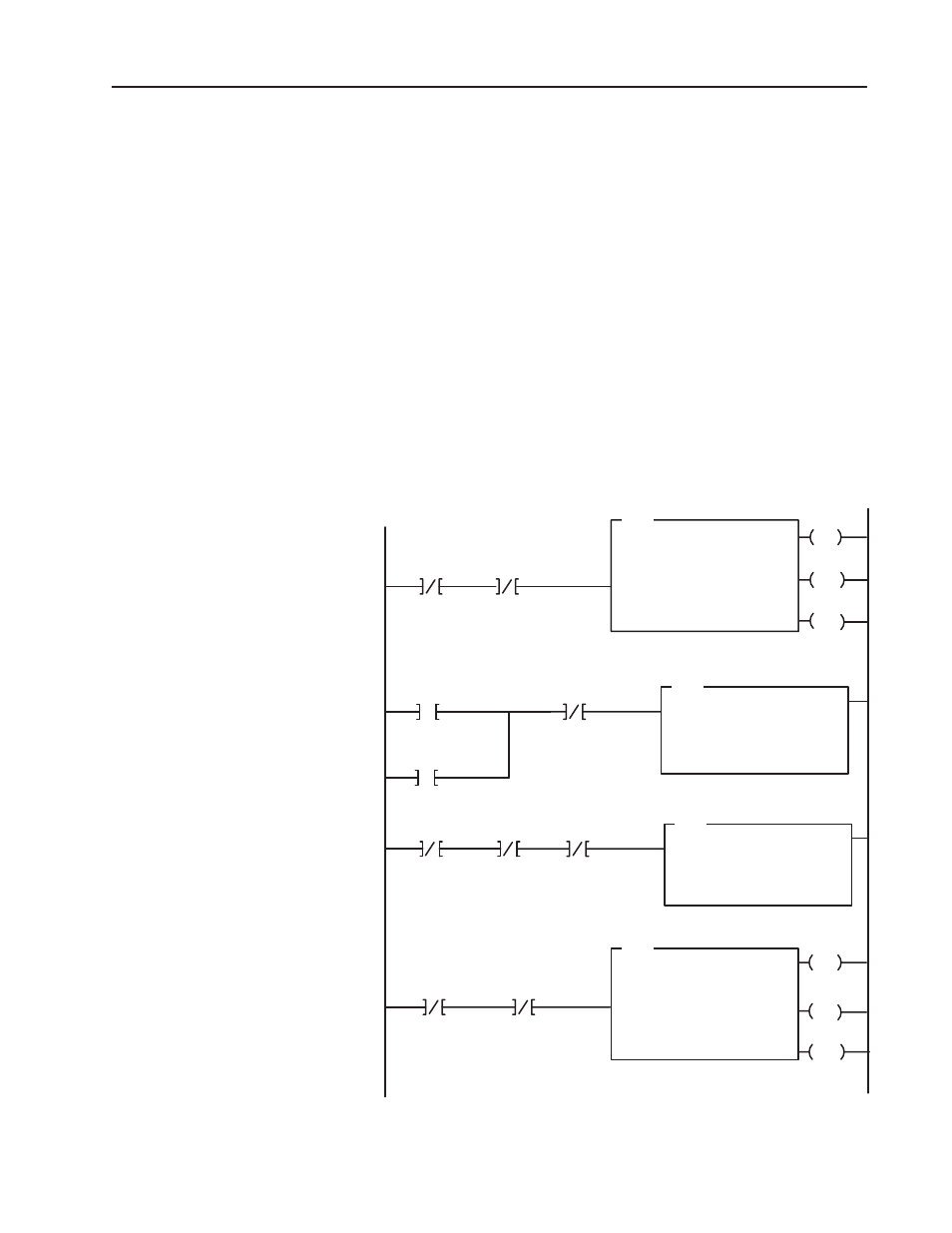
Sample Ladder Diagram Ć PLCĆ3 FamilyProcessors
The following PLC-3 program can be used for all 1771-N series
modules. The program can be altered to effectively address modules
with or without output channels.
Figure 3.4
PLCĆ3 FamilyExample Program Structure
EN
BTR
BLOCK XFER READ
RACK:
GROUP:
MODULE:
DATA FILE
0
0
0
#N1:0
LENGTH:
CONTROL:
0
#B1:10
EN
DN
B1:10
05
Block Transfer
Read Done Bit
ER
Enable
Done
Error
12
15
13
Enable
Done
Error
02
05
03
Block Transfer
Write Done Bit
Rung1
DN
ER
B1:10
15
MOV
SOURCE:
DESTINATION:
B1:0
B1:15
Pushbutton
00
Power-up Bit
17
B1:10
07
MOV
SOURCE:
DESTINATION:
B1:1
B1:15
Pushbutton
00
17
B1:10
07
Block Transfer
Write Done Bit
0000000000001001
Block
Transfer
Write Done Bit
0000000000111011
13
Block Transfer
Read Error Bit
B1:10
Rung2
Rung3
Rung4
BTW
BLOCK XFER WRITE
RACK:
GROUP:
MODULE:
DATA FILE
0
0
0
#N1:100
LENGTH:
CONTROL:
9
#B1:10
03
Block Transfer
Write Error Bit
B1:10
I0:2
N1:1
I0:2
Power-up Bit
N1:1
0000000000001001
0000000000001001
This program changes the length of the block transfer write from 59 words at powerup
or when reconfigured, to 9 words at all other times.