Rockwell Automation 1771-N SERIES High Resolution Analog Module User Manual User Manual
Page 53
4–13
Configuring the Module
Publication 1771ĆUM127B-EN-P - December 2002
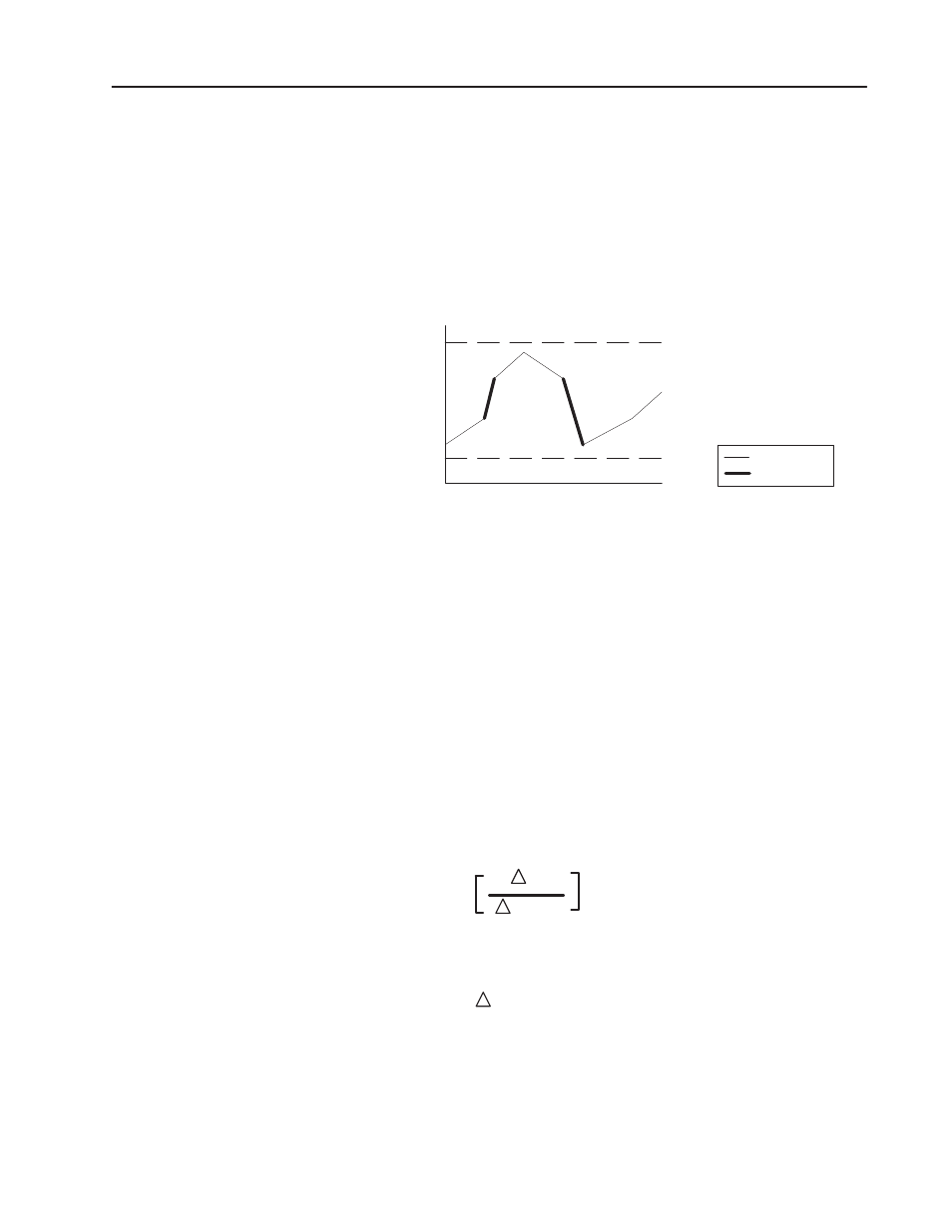
Rate Alarm
This bit is set when the input changes at a rate faster than the
user-defined value. Rate of change values can range from 0.05% to
50% of the input’s full scale range per second. Full scale range is
defined as the difference between the high scale value and the low
scale value. The rate is specified in scaled units per second.
Figure 4.5
Rate of Change Alarm
High Alarm Limit
Input Channel
Low Alarm Limit
Time
Select the change in input
that should activate the alarm
to alert the user of potential
problems.
alarm active
alarm inactive
Digital Filtering
This value specifies the time constant for a digital first order lag
filter on the input. It is specified in units of 0.1 seconds. Values range
from 0.1-9.9 seconds in BCD and 0.1-10.0 seconds in binary. A
value of 0 disables the filter.
The digital filter equation is a classic first order lag equation
(Figure 4.6). Using a step input change to illustrate the filter
response (Figure 4.7), you can see that when the digital filter
constant time elapses, 63.2% of the total response is reached. Each
additional time constant achieves 63.2% of the remaining response.
Figure 4.6
Digital Filter Equation
Y
n
= Y
n-1
+
t
t + TA
(X
n
– Y
n-1
)
Where: Yn = present output, filtered peak voltage (PV)
Yn -1 = previous output, filtered PV
t = module channel update time (seconds)
X n = present input, unfiltered PV
TA = digital filter time constant (seconds)