Sample ladder diagram ć plcć5 familyprocessors – Rockwell Automation 1771-N SERIES High Resolution Analog Module User Manual User Manual
Page 38
3–6
Communicating With Your Analog Module
Publication 1771ĆUM127B-EN-P - December 2002
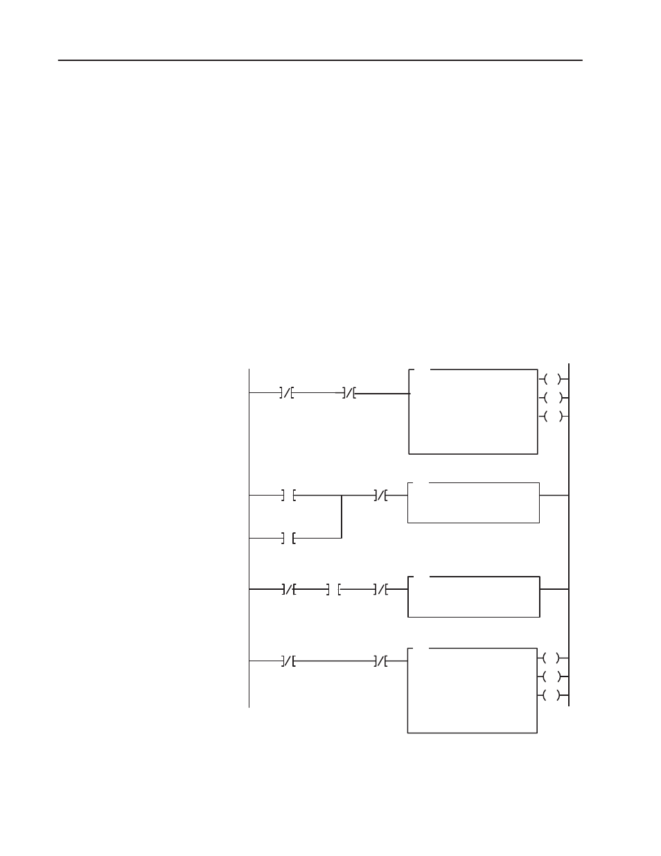
Modules without output channels do not require rungs 2 and 3.
Instead, move the input condition instructions from rung 2 to the
front of rung 4, and specify the BTW length equal to 59.
Sample Ladder Diagram Ć PLCĆ5 FamilyProcessors
The following PLC-5 program is very similar to the preceding
PLC-3 program with the following exceptions:
•
You use enable bits instead of done bits as the conditions on each
rung.
•
A separate control file must be selected for each of the block
transfer instructions.
Figure 3.5
PLCĆ5 FamilyExample Program Structure
EN
BTR
BLOCK XFER READ
RACK:
GROUP:
MODULE:
CONTROL:
01
00
0
N10:0
DN
DATA FILE:
LENGTH:
CONTINUOUS:
N10:10
00
N
ER
BTR Enable
15
1
EN
BTW
BLOCK XFER WRITE
RACK:
GROUP:
MODULE:
CONTROL:
01
00
0
N10:5
DN
DATA FILE:
LENGTH:
CONTINUOUS:
N10:80
N
ER
15
15
2
BTW
Enable
BTW Enable
15
CPT
COMPUTE
DEST
EXPRESSION
N10:6
59
00
15
BTW
Enable
Pushbutton
15
Powerup Bit
* Length = (number of outputs + 1) words.
For 2 output/6 input modules, this would be equal to 3.
*
4
BTR
Enable
N10:0
N10:5
N10:11
I:007
N10:5
N10:0
N10:5
3
CPT
COMPUTE
DEST
EXPRESSION
N10:6
9
00
15
BTW
Enable
Pushbutton
I:007
N10:5
For the followingexample, assume the analogmodule is physically located at rack address 01, module group 00, module slo
and the input module connected to the pushbutton is located at rack address 00, module group 7, slot 6. The block transfer
data files correspond to the example on the followingpages.
Modules without output channels do not require rungs 2 and 3. Instead, move
the input
condition instructions (pushbutton and powerup) from rung2 to the front of rung
4, and specify the BTW length equal to 59.
15
Powerup Bit
N10:11