Rockwell Automation 1771-N SERIES High Resolution Analog Module User Manual User Manual
Page 35
3–3
Communicating With Your Analog Module
Publication 1771ĆUM127B-EN-P - December 2002
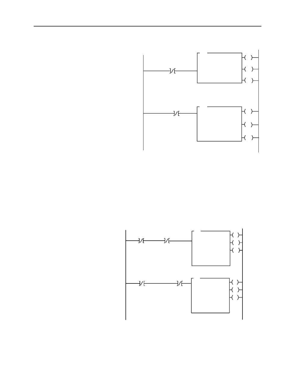
Figure 3.1
PLCĆ3 FamilySample Program Structure
EN
BTR
BLOCK XFER READ
RACK:
GROUP:
MODULE:
DATA:
XXX
X
X = XXXX
XXXX:XXXX
LENGTH:
CNTL:
00
XXXX:XXXX
EN
BTW
BLOCK XFER WRITE
RACK:
GROUP:
MODULE:
DATA:
XXX
X
X = XXXX
XXXX:XXXX
DN
LENGTH:
CNTL:
00
XXXX:XXXX
Block Transfer
Read Done Bit
ER
Enable
Done
Error
12
15
13
Enable
Done
Error
02
05
03
Block Transfer
Write Done Bit
1
2
DN
ER
Program Action
At powerup, the user program enables a
block transfer read. Then it initiates a
block transfer write to configure module.
Thereafter, the program continuously perĆ
forms read and write block transfers.
This program is very similar to the PLC-3 program with the
following exceptions:
•
Block transfer enable bits are used instead of done bits as the
conditions on each rung.
•
Separate block transfer control files are used for the block
transfer instructions.
Figure 3.2
PLCĆ5 FamilySample Program Structure
EN
BTR
BLOCK XFER READ
RACK:
GROUP:
MODULE:
CONTROL:
X
X
X
XXX:XX
DN
DATA FILE:
LENGTH:
CONTINUOUS:
XXX:XX
00
N
ER
BTR Enable
1
EN
BTW
BLOCK XFER WRITE
RACK:
GROUP:
MODULE:
CONTROL:
X
X
X
XXX:XX
DN
DATA FILE:
LENGTH:
CONTINUOUS:
XXX:XX
00
N
ER
BTR
2
BTW
Enabl
e
BTW Enable
Enable
Program Action
At powerup, the user program enables a
block transfer read. Then it initiates a block
transfer write to configure module.
Thereafter, the program continuously perĆ
forms read and write block transfers.
PLCĆ5 and PLCĆ5/250
Program Example