Rockwell Automation 1771-N SERIES High Resolution Analog Module User Manual User Manual
Page 18
1–4
Overview of the High Resolution Isolated Analog Modules
Publication 1771ĆUM127B-EN-P - December 2002
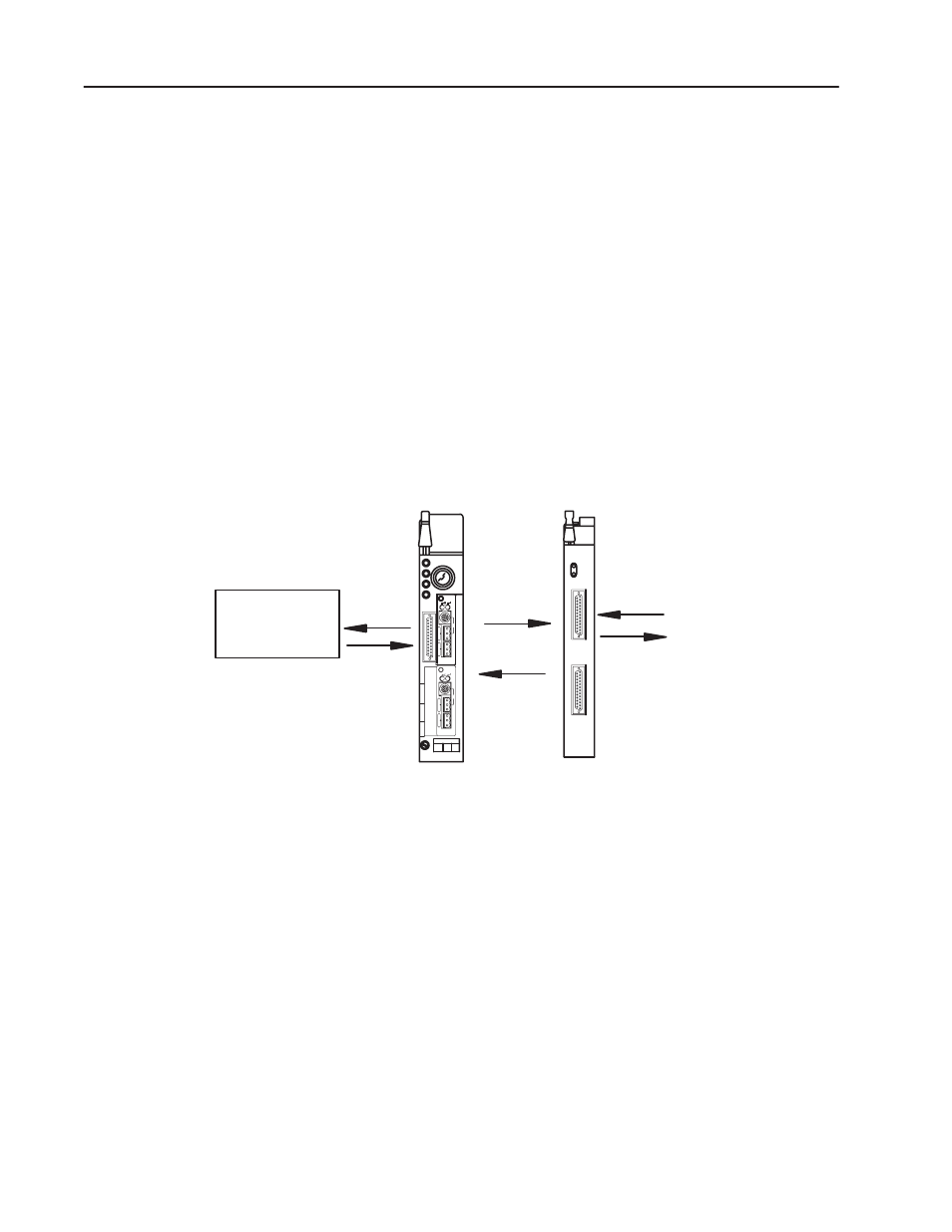
The processor transfers data to and from the module using BTW
(block transfer write) and BTR (block transfer read) instructions in
your ladder diagram program. These instructions let the processor
obtain input values and status from the module, and let you establish
the module’s mode of operation (Figure NO TAG).
1. The processor transfers your configuration data, output data and
calibration values to the module using a block transfer write
instruction.
2. External input devices generate analog signals that are transmitted
to the module. Internal output circuitry generates analog signals
that drive field devices.
3. The module converts the analog signals into binary or BCD
format and stores theses values until the processor requests their
transfer.
Table 1.A
Communication Between the Processor and the Module
Memory
User Program
PLC Processor
(PLCĆ5/40 Shown)
High Resolution
Isolated Analog
Module
BTW
BTR
5
2
3
12933ĆI
1
4
From input devices
To output devices
4. When instructed by your ladder program, the processor performs
a read block transfer of the values and stores them in a data table.
5. The processor and module determine that the transfer was made
without error, and that input values are within specified range.
6. Your ladder program can use and/or move the data (if valid)
before it is written over by the transfer of new data in a
subsequent transfer.
See chapter 4, “Configuring the Module,” for more information.
The accuracy of each of the high resolution isolated analog modules
is described in Appendix A.
In this chapter you read about the functional aspects of the analog
modules and how they communicate with programmable controllers.
How the High Resolution
Isolated Analog Modules
Communicate with
Processors
Accuracy
Chapter Summary