Rockwell Automation 1771-N SERIES High Resolution Analog Module User Manual User Manual
Page 21
2–3
Installing the Module
Publication 1771ĆUM127B-EN-P - December 2002
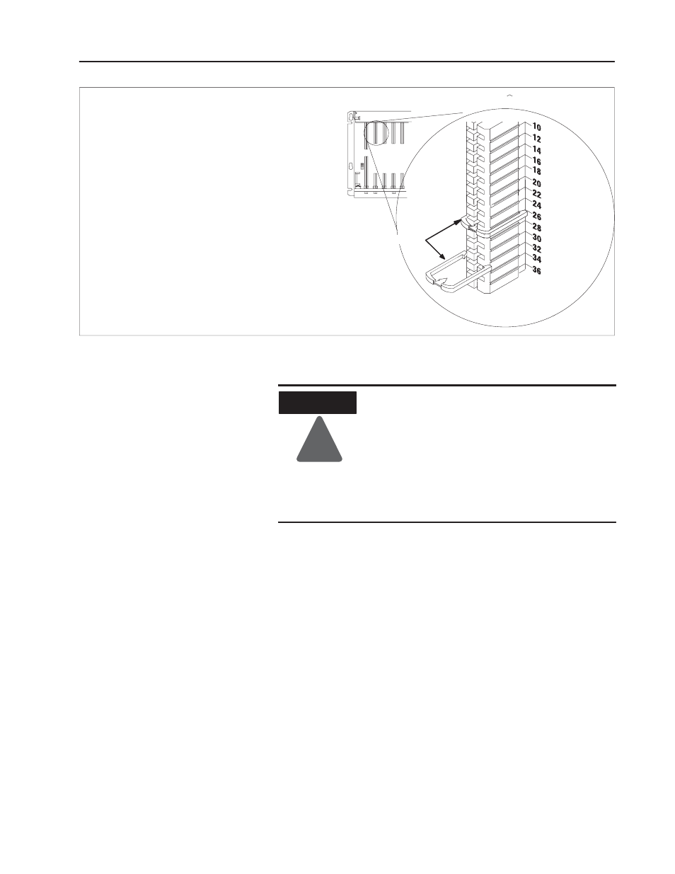
Position the keyingbands in the backplane connectors
to correspond to the key slots on the module.
Place the keyingbands:
between 26 and 28
between 32 and 34
You can change the position of these bands if
subsequent system design and rewiring makes
insertion of a different type of module necessary.
11022ĆI
I/O chassis
Place your module in any slot in the chassis
except the leftmost slot which is reserved for
processors or adapters.
Keythe Backplane Connector
Upper Connector
KeyingBands
ATTENTION
!
Remove power from the 1771 I/O chassis
backplane and field wiring arm before removing
or installing an I/O module.
•
Failure to remove power from the backplane or
wiring arm could cause module damage, degra-
dation of performance, or injury.
•
Failure to remove power from the backplane
could cause injury or equipment damage due to
possible unexpected operation.
1. Place the module in the plastic tracks on the top and bottom of the
slot that guides the module into position.
2. Do not force the module into its backplane connector. Apply firm
even pressure on the module until it is firmly seated in the
chassis. Note: The chassis locking bar will not close if all
modules are not seated properly.
Install the Module in the
Chassis and Connect the
Cable