Rockwell Automation 140G-NTK-E12 LSIG and LSIG-MM Release User Manual
Page 9
DIR 1000587R0002 (L3821)
(9)
Ref.
Description
21
Test and “i Test” info button
22
Position indicator of DIP switches for setting time t2
23
DIP switch for setting trip time t2 and type of curve
24
Position indicator of DIP switches for setting time t1
25
DIP switch for setting trip time t1
26
Rating plug
27
DIP switch for setting mains frequency and adjusting neutral protection
2.4.1 Trip Test
Before commissioning, run a test (“Trip Test”) on the whole TC chain by pressing and holding button “iTest” pressed for at least 7 sec. A positive
outcome is shown by circuit-breaker opening (see Watchdog). To run the test, battery unit must be connected.
2.4.2 Initial settings
AB will have the adhesive labels affixed onto the LSIG for all variables relating to circuit breaker (e.g. Type of circuit breaker, Rating Plug size, etc.)
Consider that AB provides a sensible definition for each possible setting (see par. 2.4.4).
Apart from this, before the LSIG unit is commissioned, user must accurately define every alterable parameter.
2.4.3 Changing protection functions
This paragraph describes setting of protection functions implemented in the LSIG unit. Only setting methods and values that can be selected are
explained here. For all other information on the technical characteristics of the protection functions, see par. 2.1.4.
No parameters can be set when the LSIG unit is in alarm conditions.
2.4.3.1
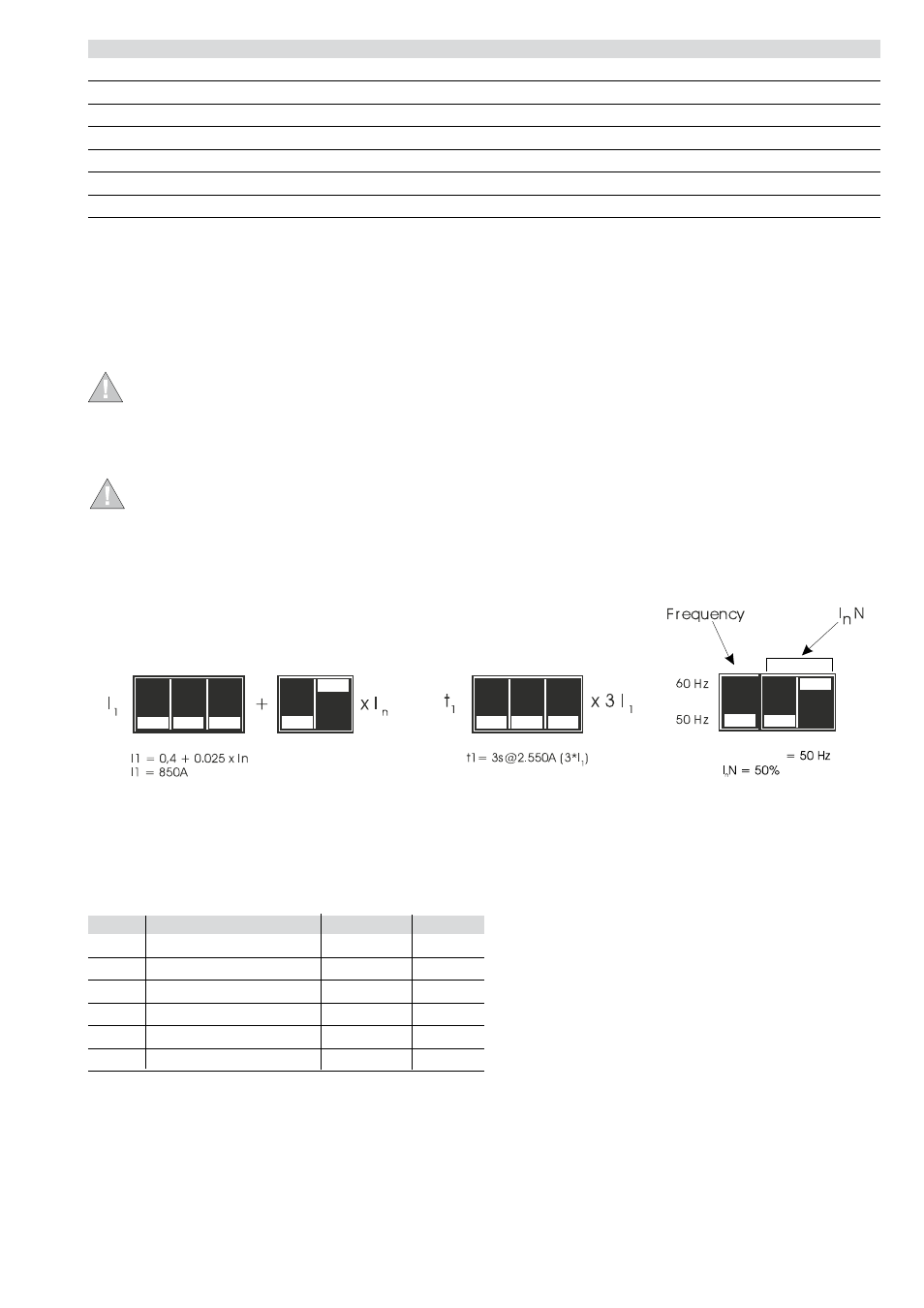
Example of setting
In the diagrams on front plate (see par. 2.4) relating to settings, the position of the DIP switch is shown in white color.
An example of how to set the DIP switch for protection function L is given below, where I
n
= 2000 A:
Incorrect configuration of DIP switches causes a “inconsistent settings” indicated by LEDs (see par. 2.6.1).
The rule to be complied with is: I1 E.g.: if I1=1In and I2=1In, the relay will indicate an “inconsistent setting” error. Same indication if I2=5In and I3=4In 2.4.4 Default setting of LSIG unit # Protection Thresholds Time 1 L 1 In 144 s 2 S Off 0.1 s 3 I 4 In — 4 G Off 0.1 s 5 Mains frequency (1) 6 Neutral Sel. (2) Note: (1) = 50 Hz for IEC type CB 60 Hz for UL type CB (2) = Off for three-pole versions 50% for 4-pole versions 2.5 Operating instructions/Operation in service 2.5.1 Adjusting the neutral Frequency
The LSIG is supplied by AB with the following predefined parameters:
Neutral protection is normally set to a current value 50% of the adjustment made on the phases.