Rockwell Automation 140G-NTK-E12 LSIG and LSIG-MM Release User Manual
Page 29
DIR 1000587R0002 (L3821)
(29)
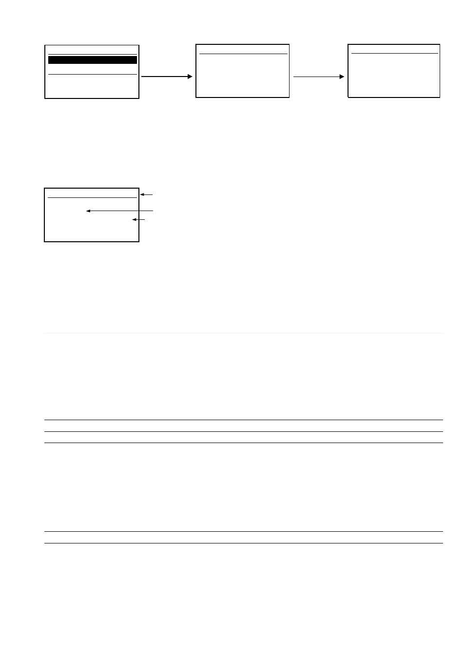
3.4.6 Information Menu
The Information Menu enables viewing data relating to protection unit and type of circuit breaker.
1/2
Protection Unit
Circuit Breaker
Protection Unit
About
Enter ↵
ESC +↓
+ Enter ↵
1/3
Protection Unit
Nr. :
Version
Normative
Software
G0000A03A
: LSIG-MM
: UL
: 2,00
Device
: LSIG-MM
1/3
Circuit Breaker
Device
Nr. :
Rated Curr.
Installation
Maintenance
: 140G-N/4p
: 1200 A
: Jan 12, 2013
: Jan 12, 2013
3.4.6.1
Information on trip and opening data
The LSIG-MM units save all information relating to type of protection tripped, opening data, date and time. Using the “i Test” key, the release
will show all these data directly on the display. There is no need for an auxiliary power supply for this function. With an auxiliary power supply,
information is shown immediately on the display without needing to press the “i Test” key, and remains displayed until the key is pressed.
Information is available for 48 hours with the relay disconnected. The data relating to the last 20 trips are stored in the unit’s memory. By connec-
ting a battery unit or you can retrieve all information relating to the last 20 trips recorded. Access to view the opening data is via the Historicals
submenu in the Measurements menu. The following is an example of the information provided:
Again in the Measurements menu, you can view the percentage of contact wear, which is an indication of the electrical life of the contacts in the
circuit breaker.
However, relay functionality is in no way modified by the presence of wear messages.
A prealarm message (wear > 80%, “warning” LED lighting up) indicates that wear has reached a high value. An alarm message (100% wear,
“alarm” LED lighting up) indicates that the state of contact wear must be checked.
The percentage of wear depends on type of circuit-breaker and number of openings performed by circuit-breaker and by absolute current inter-
rupted during each opening.
3.5
Definition of alarms and signals for the LSIG-MM units
3.5.1
Optical signals
Signalling
Description
Warning (yellow permanent)
•The prealarm threshold has been exceeded; one or more phases with current values in the range 0.9xI
1
< I
LED
< 1.05xI
1
(on the Ne, it depends on selection made; e.g. at 50%, values are halved);
• Presence, between two or three phases, of unbalance above the value programmed for “U” protection,
with protection trip disabled;
• Presence of distorted wave form with form factor > 2.1;
• Contact wear greater than 80% (and less than 100%);
• WARNING Threshold I
w
exceeded;
• Circuit-breaker state error;
•Configuration error;
• Settings inconsistency.
Warning LED (yellow 0.5 Hz)
• WARNING threshold for temperature inside relay is exceeded.
Warning LED (yellow 2 Hz)
• ALARM threshold for temperature inside relay is exceeded.
• Presence of one or more overloaded phases with current values I>1.3 I1 (protection “L” timing)
(on the Ne, it depends on selection made; e.g. at 200%, values are doubled)*;
• Timing in progress for protection function S;
• Timing in progress for protection function G;
Alarm LED (red)
• Timing when unbalance between phases (protection U) exceeds the value set in the configuration with
protection trip set to on;
• Contact wear = 100%;
• Rating Plug disconnected;
• Trip Coil (TC) disconnected;
• Key plug error;
• Current sensors disconnected;
• Installation error.
* IEC 60947-2 Standard defines timing threshold L for current: 1.05 < I < 1.3 I1
n. 02
L Protection
I1:
625 A
I3:
623 A
I2:
617 A
Ne: > 10.0 kA
Jan 06, 2013
08:52:11:733
Last Trip
Number of openings due to protections and TRIP tests
Indication for protection tripped
Value of the currents interrupted on phases (L1, L2, L3), neutral (Ne) and Ground (if G has been tripped).