Rockwell Automation 140G-NTK-E12 LSIG and LSIG-MM Release User Manual
Page 10
DIR 1000587R0002 (L3821)
(10)
In some installations, where particularly high harmonics occur, the current running on neutral may be higher than that of phases.
In the LSIG release, this protection can be set for the following values: I
n
N =0 - 50% - 100% - 200% * I
n.
With three-pole circuit breakers, without external neutral, Neutral is adjusted to OFF
2.5.2 Guidance for Neutral adjustment
Adjustment of neutral value (I
n
N) must comply with the following formula: I
1
x I
n
N≤Iu
When a 4-pole CB is available, this setting is controlled by the relay which signals the fault through a LED (see par. 2.6.1), and automatically
adjusts the parameter within the accepted limits.
When a 3-pole CB with external neutral is available, the relay does not perform any control and settings are to be adjusted by user.
E.g.:
With 140G-N 1200 with Rating Plug at 400 A, Iu=1200 A and I1=1In, adjustment of I
n
N may be 50-100-200%
With 140G-N 1200 and 800 A Rating Plug, Iu=1200 A and I1=1In, adjustment of I
n
N may be 50-100%
Note 1: I
1
=1l
n
setting is intended as the maximum adjustment of the protection against overloads. Actual maximum allowable adjustment must take into account any tempe-
rature derating, terminals used and altitude, or In (rating plug)≤ 50% of circuit breaker size.
Failure to comply with the setting limits for “I1“ and “I
n
N” can cause damage to circuit breaker with consequent risks even for
operator.
2.5.3 Replacing an electronic release
To complete the procedure for installing LSIG, take the following steps:
1. With the circuit breaker open and preferably isolated, install the protection unit on the circuit breaker.
2. Power the unit ONLY from the battery unit.
3. If there are no errors other than configuration error (see par. 2.6.1), press and hold “i Test” button for a few seconds until all red LEDs
start flashing confirming that installation is completed.
4. Remove the battery unit.
5. Power the relay from any supply (Vaux, battery unit).
6. Make sure there are no configuration errors (“Alive” LED glows).
7. Circuit breaker and release can now be commissioned.
2.6 Definition of alarms and signals for the LSIG unit
2.6.1 Optical signals
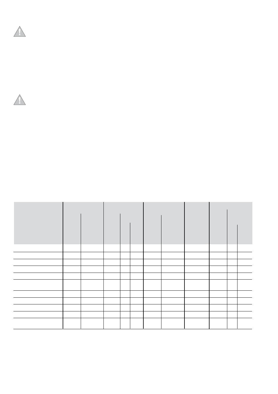
The following table shows how the LEDs are managed in accordance with IEC 60073 standard (clause 4.2.3.2 in particular).
The LED alerts about status of the function set on its zone; e.g. in the figure in par. 2.5 the LED referenced as 8 identifies status of function L.
Also see the following table
LED permanently ON
TC error or TC disconnected
CS error or disconnected
Rating Plug/Installation error
(1)
Protection timer error
Last trip
(2)
Test button pressed and
no failure detected
(3)
L pre-alarm
Configuration error
(4)
Settings inconsistency
Normal operation of relay
(5)
CB Undefined or
CB status error
RED
Flashing
slowly (0.5 Hz)
RED
RED
RED
ORANGE
RED
RED
ORANGE
Type of information
All LEDs
All LEDs
All LEDs
All LEDs
Single LED
Single LED
Flashing fast (2Hz)
LED flashing with
two 0.5 sec pulses
every 2 sec
ORANGE
Single LED
LED flashing with
one pulse
every 3 sec
ORANGE
Single LED
LED permanently ON
Single LED
ORANGE
(1) RP disconnected or RP>Iu
(2) Information on the “Last trip” is displayed when the LED relating to the protection unit that has been tripped comes on. The LED remains on
for 2 sec, or permanently if an outside power supply (from battery unit) is being used.
(3) The information is displayed with all LEDs on for as long as the test button is pressed and held, or for 2 sec.
(4) Installed values differ from stored values. Therefore, the relay must be installed (see 2.5.3).
(5) If other signals aren’t present, the unit’s operating mode is indicated 3 sec after the unit has been turned on.