Rockwell Automation 140G-NTK-E12 LSIG and LSIG-MM Release User Manual
Page 41
DIR 1000587R002 (L3821)
Pubblication 140G-IN067A-MU-P - April 2013
5.1.4 Data Logger commands from system
As a consequence of a Stop Data Logger command, storage will be stopped from system. Any subsequent recording is enabled following a
Restart trigger command. The same operations can be performed from the operator panel as given in par. 5.1.2.6.
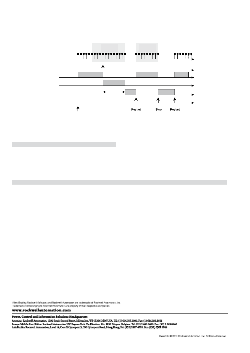
Example of Data Logger operation
The following figure shows an example of how trigger and Data Logger operate, and influence of stopping delay and restart and subsequent
stoppage of the data storage phase.
Samples
Samples
available
Samples
available
Trigger
Waiting Trigger
Modbus commands
Datalogger Triggered
Datalogger Stopped
Stopping
delay
Data logger enabled
5.2 Event list table
5.2.1 “Standard” events for the Data Logger function, selectable from the relay
Event no.
Description
0.
None
(free running)
1.
Any alarm
2.
L timing
(L protection timing)
3.
Any trip
(tripping of any protection)
5.2.2 Examples of “custom” events for Data Logger function
No. (decimal)
Event
Notes
LSIG-MM
1920
G timing
x
2894
L1 or L2 or L3 sensor error or Trip Coil error
x
2688
LC1 alarm
x
2049
G alarm
x
33672
CB connected and spring loaded
x
1793
Harmonic distortion > 2.1
x
You can combine the status bits with “and” / “or” logical functions within the same group of events (byte). For more detailed information, refer to
the Modbus Interface document.
5.2.3 Combining the devices needed to customize settings
“Custom” events can be selected using a remote control system.
The devices needed to do so can be selected from among the following:
LSIG-MM + Dialog unit