Rockwell Automation 140G-NTK-E12 LSIG and LSIG-MM Release User Manual
Page 7
DIR 1000587R0002 (L3821)
(7)
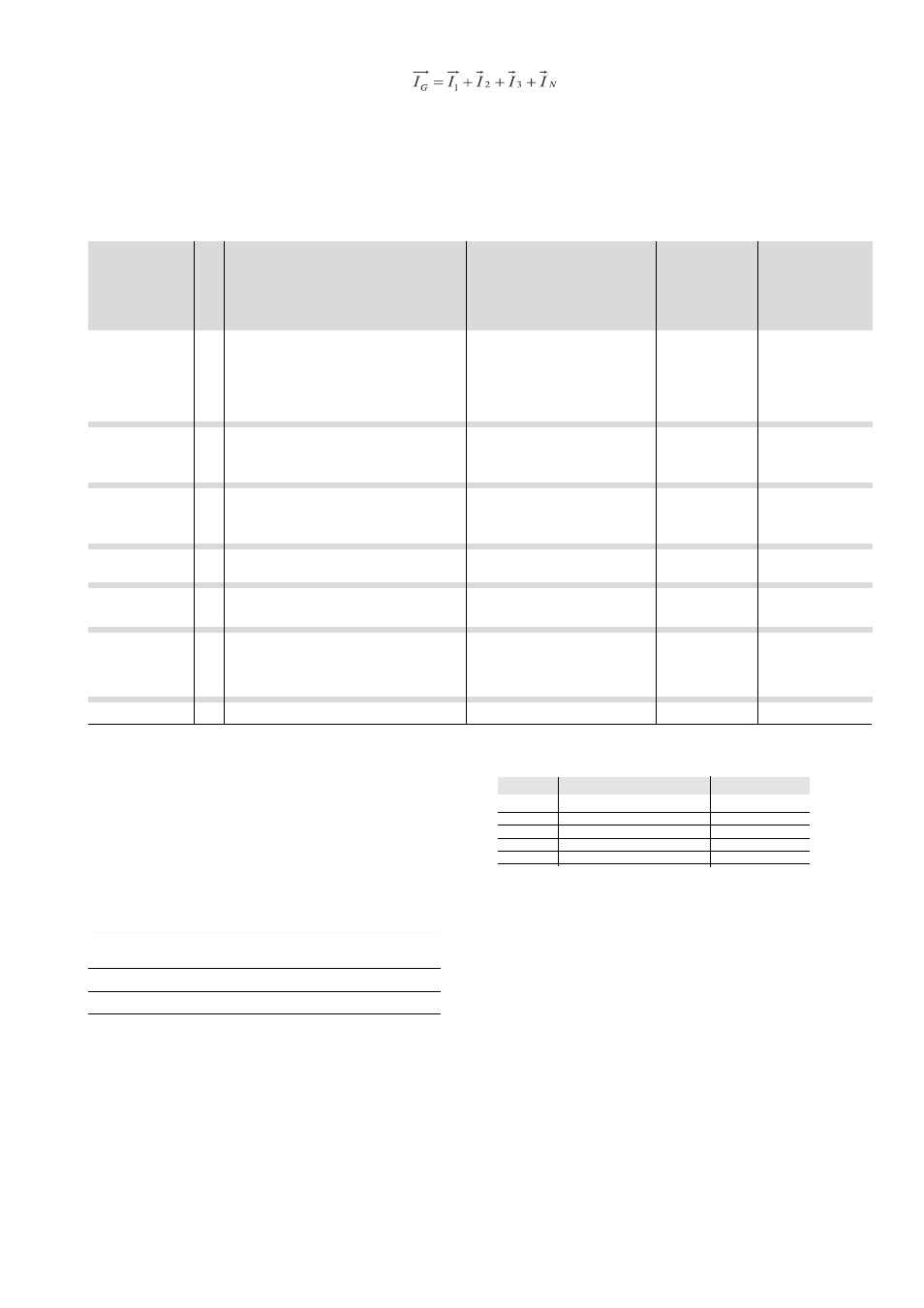
The LSIG unit can provide earth fault protection, achieved inside the relay by vectorially adding together phase and neutral currents. Fault current
is defined by the following formula:
If the circuit shows no faults, the module of the sum of these currents is always nil; vice versa, the value of the fault current takes on a larger and
larger value depending on size of fault.
2.1.5.5
Protection against instantaneous short-circuit “Iinst”
This function has a single fixed-time protection curve.
When the protection is tripped, the circuit breacker is opened by the opening solenoid (TC).
2.1.6 Summary table of protections
(1)
The minimum value of this trip is 1s regardless of the type of curve set (self-
protection).
(2)
These tolerances apply under the following conditions:
- self-powered relay at full power (without start-up)
- presence of auxiliary power supply
- two-phase or three-phase power supply
- preset trip time
≥100ms
(3)
The value of this trip is ensured inside the time window ranging from 40 to
500 ms from CB closing; this setting must be done by customer.
For all cases not covered by the above assumptions, the following tolerance
values apply
Protections
Trip threshold
Trip time
L
Release between 1.05 and 1.25 x I1 ± 20%
S
± 10%
± 20%
I
± 15%
≤ 60 ms
G
± 10%
± 20%
Others
± 20%
Disabling
Trip threshold
Trip time
Trip threshold
tolerance
(2)
Protection
Trip time
tolerance
(2)
L
I1 = 0.4 - 0.425 - 0.45 - 0.475 - 0.5 -
Release between
(t=k/I
2
)
0.525 - 0.55 - 0.575 - 0.6 - 0.625 -
t1 = 3 - 12 - 24 - 36 - 48 - 72
1.05 and 1.2 x I1
± 10% I
g
≤ 6 x In
0.65 - 0.675 - 0.7 - 0.725 - 0.75 -
108 - 144 s
(1)
± 20% I
g
> 6 x In
0.775 - 0.8 - 0.825 - 0.85 - 0.875 -
@ 3 I1
0.9 - 0.925 - 0.975 - 1 x In
S
I2 = 0,6 - 0,8 - 1,2 - 1,8 - 2,4 - 3 - 3,6 - 4,2
with I > I2
± 7% I
g
≤ 6 x In
The best of the two data:
(t=k)
5 - 5,8 - 6,6 - 7,4 - 8,2 - 9 - 10 x In
t2 = 0.1 - 0.2 - 0.3 - 0.4 - 0.5 - 0.6 ± 10% I
g
>6 x In
± 10% or ± 40 ms
0.7 - 0.8 s
S
I2 = 0,6 - 0,8 - 1,2 - 1,8 - 2,4 - 3 - 3,6 - 4,2 t2 = 0.1 - 0.2 - 0.3 - 0.4 - 0.5 - 0.6 ± 7% I
g
≤ 6 x In ± 15% I
g
≤ 6 x In
(t=k/I
2
)
5 - 5,8 - 6,6 - 7,4 - 8,2 - 9 - 10 x In
0.7 - 0.8 s
± 10% I
g
>6 x In ± 20% I
g
>6 x In
@ 10 In
I
I3 = 1,5 - 2 - 3 - 4 - 5 - 6 - 7 - 8 - 9 - 10 -
≤ 30 ms
± 10%
(t=k)
11 - 12 - 13 - 14 - 15 x In
G
I4 = 0.2 - 0.3 - 0.4 - 0.6 - 0.8 - 0.9 -
with I > I4
± 7%
The best of the two data:
(t=k)
1 x In
t4 = 0.1 - 0.2 - 0.4 - 0.8 s
± 10% or ± 40 ms
t4 = 0.1@ 4.47 I4
G
I4 = 0.2 - 0.3 - 0.4 - 0.6 - 0.8 - 0.9 -
t4 = 0.2@ 3.16 I4
± 7%
± 15%
(t=k/I
2
)
1 x In
t4 = 0.4@ 2.24 I4
t4 = 0.8@ 1.58 I4
I inst
Automatic, defined by AB
Instantaneous
2.1.7 Measurements
The LSIG protection unit can perform different types of measurements shown in the following table with relevant tolerances.
Type of measurement
Tolerance
Range
%
Phase and neutral current
0.3 ... 6 In
1.5
Earth fault current
0.3 ... 4 In
1.5
2.2 Other functions
2.2.1 Indication of trip cause and trip test button
Using the “i Test” button, any information stored in the past 48 hours can be retrieved. In addition, a trip test can be obtained by keeping the button
pressed for 7 seconds, and autotest by keeping button pressed for 3 seconds, with battery unit on and with no running current.