Lsig release - identification – Rockwell Automation 140G-NTK-E12 LSIG and LSIG-MM Release User Manual
Page 5
DIR 1000587R0002 (L3821)
(5)
2.1 Specifications
2.1.1 General
The LSIG unit is a high-performance self-powered protection unit with Protection functions for the AB 140G-N/140G-NS/140G-R range of 3-pole
and 4-pole low voltage circuit-breakers. The unit’s user interface also enables parameter setup and full pre-alarm and alarm management with
LED warning/alarm indicators for protection and watchdog functions.
Depending on the version, the protections available are as follows:
Symbol
Protection against
L
overload with inverse long time delay
S
short-circuit with adjustable delay
I
instantaneous short-circuit
G
earth fault with adjustable delay
The LSIG can be installed on 3-pole CBs with and without an external neutral, or on 4-pole CBs.
It should be noted that the reference current for LSIG is In (rated current defined by Rating Plug) and not Iu (uninterrupted rated current of the
CB itself).
Example: CB 140G-N 1200 with a 400 A Rating Plug has an Iu of 1200 A and an In of 400 A.
The unit opens the circuit breaker in which it is installed by means of the TC, which operates directly on the device’s mechanical linkage.
The unit is made using a digital microprocessor technology and interfaces with user by means of DIP switches. The unit’s protection parameters
and general operating mode can be set by user.
2.1.2 Electrical characteristics
Rated operating frequency
50/60 Hz ±10%
Pass band
3000 Hz max
Peak factor
6.3 max @ 2 In
2.1.2.1 Self-powering
The unit requires no outside power source for protection and alarm signal functions. It is self-powered by current sensors installed on circuit
breaker. Operation simply depends on current defined below running through at least one phase. An outside power source can be connected
to enable other functions.
The characteristics of the busbar current are given in the table below.
Characteristics
Enabling the relay
Minimum three-phase busbar current to enable the relay (Led alive enable and full relay operation)
>80 A
2.1.2.2
Auxiliary power supply
External auxiliary power supply is provided using a galvanically-separated power pack.
Since auxiliary voltage needs to be isolated from the ground, “galvanically separated converters” in accordance with IEC
standard 60950 (UL 1950) or equivalent IEC 60364-41 and CEI 64-8, have to be used to guarantee a current in common mode
or leakage current (as defined in IEC 478/1 and CEI 22/3) no greater than 3.5 mA.
Presence of the auxiliary power supply enables the relay unit to be used even with circuit breaker open.
The characteristics of the power pack are given in the table below.
Characteristics
LSIG Version
Auxiliary voltage
(galvanically separated)
24 V DC ±20%
Maximum ripple
5%
Inrush current @ 24 V
~2 A for 5 ms
Rated power @ 24 V
~2 W
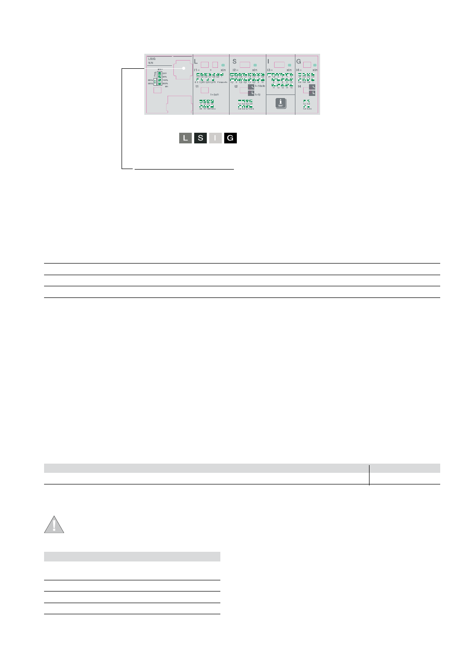
2. LSIG Release - Identification
The LSIG units available with protections and optional modules, are shown in the following figure.
Protections
Optional modules available
Battery unit