Rockwell Automation 140G-NTK-E12 LSIG and LSIG-MM Release User Manual
Page 27
DIR 1000587R0002 (L3821)
(27)
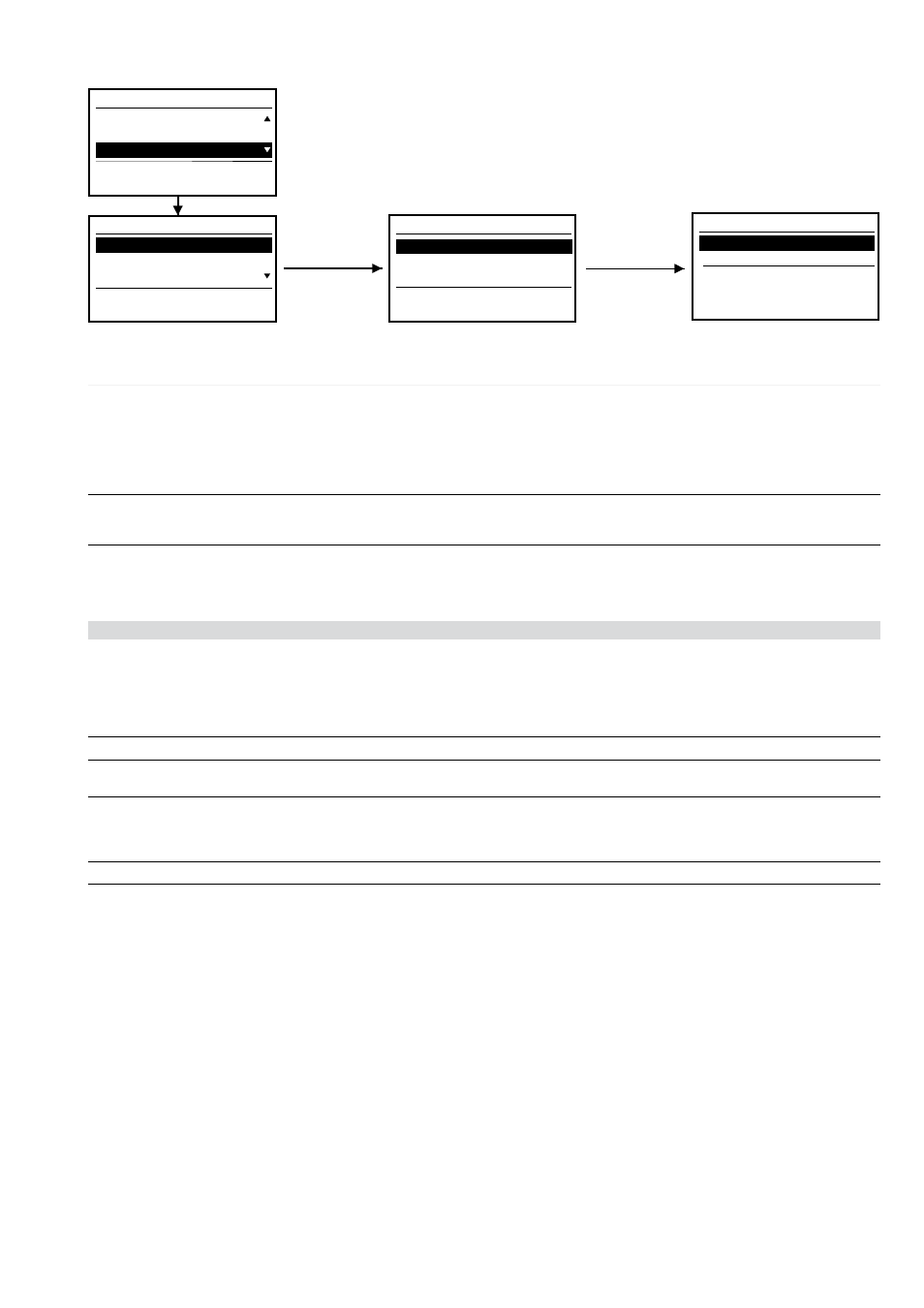
3.4.4 Settings Menu
The configuration parameters in the Settings menu are password-protected. Among the most
significant values that can be selected, note the neutral threshold (values 50%, 100%, 150%,
200%), mains frequency of installation (values 50 Hz, 60 Hz). For a more detailed description of
the settings for the modules, refer to the documentation on the modules (ch. 4).
1/5
Protections settings
Measurements
Settings
Protections
Menu
1/9
Circuit breaker settings
Main Frequency
Modules
Circuit Breaker
Settings
1/3
Neutral settings
Neutral Protection
Unit installation
Ground protection
Circuit Breaker
On
Neutral threshold
Enable
Neutral protection
2
1/2
Enter ↵
Enter ↵
Enter ↵ + PWD
3.4.4.1
Settings Menu table
Parameter/Function
Values
Notes
Circuit
(*) Neutral protection
breaker
Enable
ON/OFF
Neutral threshold
50%-100%-150%-200%
Mains frequency
50 Hz - 60 Hz
Modules
Module
Communication module
if installed
see par. 3.4.4.4.2
Local Bus unit
Installed-Not installed
(*) With the three-pole circuit breaker, the “3P+N” option is displayed and must be enabled if the outside neutral is installed.
Parameter/Function
Values
Notes
Data Logger Enable
ON/OFF
See Annex par. 5.1
Sampling frequency
Trigger
Stopping delay
Restart
Stop
Measurement interval
from 5 to 120 min, step 5 min
Harmonic distortion
ON/OFF
The warning indicates that the distortion exceeds
factor 2.1
System
Date
Time
Language
English/Italiano/Français/Deutsch/Español
New password
Display
Contrast
3.4.4.2
Adjusting the neutral
Neutral protection is normally set to a current value 50% of the adjustment made on the phases.
In some installations, where particularly high harmonics occur, the current running on neutral may be higher than that of phases.
In the LSIG-MM releases, this protection can be set for the following values: I
n
N = 50% - 100% - 150% - 200% * I
n
.
The values that can be used to adjust the neutral are given in the table below for the various possible combinations between types of circuit-
breaker and adjustment of threshold I
n
.
Neutral value (InN) adjustment will meet the following formula: I
1
x I
n
N
≤Iu
When a 4-pole CB is available, this setting is controlled by the relay which signals the fault through a LED (see par. 3.5.1) , and automatically
adjusts the parameter, within the accepted limits.
When a 3-pole CB with external neutral is available, the relay does not perform any control and settings are to be adjusted by user.
E.g.:
With 140G-N 1200 with Rating Plug at 400A, Iu=1200A and I1=1In, adjustment of I
n
N may be 50-100-200%
With 140G-N 1200 with Rating Plug at 800A, Iu=1200A and I1=1In, adjustment of I
n
N may be 50-100%
Note 1: I
1
=1I
n
setting is intended as maximum adjustment of protection against overloads. Actual maximum allowable adjustment must take into account any temperature
derating, terminals used and altitude, or In (rating plug)
≤ 50% of circuit breaker size.