Rockwell Automation 140G-NTK-E12 LSIG and LSIG-MM Release User Manual
Page 17
DIR 1000587R0002 (L3821)
(17)
L
(t=k/I
2
)
0.4xIn
≤ I
1
≤ 1xIn
3s ≤ t
1
≤ 144s
(1)
, step 3s
Release between
± 10%, I
f
≤
6 In
curves IEC60255-3
step 0.01xIn
t1@ 3I
1
1.05 and 1.2xI1
± 20%, I
f
> 6 In
S
1
0.6 xIn ≤ I
2
≤10xIn
Min, 0.05s ≤ t
2
≤ 0.8s, step 0.01s
± 7%,I
g
≤ 6 In
The best of the two data
(t=k)
step 0.1xIn
0.10s ≤ t
2start-up
≤ 30s, step 0.01s
± 10%,I
g
> 6 In
± 10% or 40 ms
0.6 xIn ≤ I
2 start-up
≤10xIn
0.04s ≤ t
2sel
≤ 0.20s, step 0.01s
step 0.1xIn
S
1
0.6xIn
≤ I
2
≤10xIn
0.05s ≤ t
2
≤ 0.8s,
± 7%,I
g
≤ 6 In
± 15%, I
g
≤
6 In
(t=k/I
2
)
step 0.1xIn
step 0.01 at 10xIn
± 10%,I
g
> 6 In
± 20%, I
g
>
6 In
I
1.5xIn ≤ I
3
≤ 15xIn
≤ 30 ms
± 10%
(t=k)
step 0.1xIn
G
(3)
0.20xIn ≤ I
4
≤1xIn
0.1s ≤ t
4
≤ 1s, step 0.05s
The best of the two data
(t=k)
step 0.02xIn
0.1s ≤ t
4 start-up
≤ 1s, step 0.02s
± 7%
± 10% or 40 ms
0.04s ≤ t
4sel
≤ 0.2s, step 0.01s
when I>I4
G
(3)
0.20xIn ≤ I
4
≤1xIn
0.1s ≤ t
4
≤ 1s, step 0.05s
± 7% ± 15%
(t=k/I
2
)
step 0.02xIn
@I
g
>4In
U
2% ≤ I
6
≤ 90%
0.5s ≤ t
6
≤ 60s, step 0.5s
± 10%
The best of the two data
(t=k)
step 1%
± 10% or 40 ms
OT
Fixed, defined
Instantaneous
± 5°C _____
(temp=k)
by AB
Iinst
Automatic, defined
Instantaneous
by AB
MM
1.5xIn ≤ I
5
≤ 4xIn
≤ 30 ms
± 10%
(t=k)
step 0.1xIn
Load control
50%÷100% step 0.05xI
1
LC1/LC2
Warning Iw
0,3÷10I
n
step 0,05xI
n
± 10%
10÷40 ms
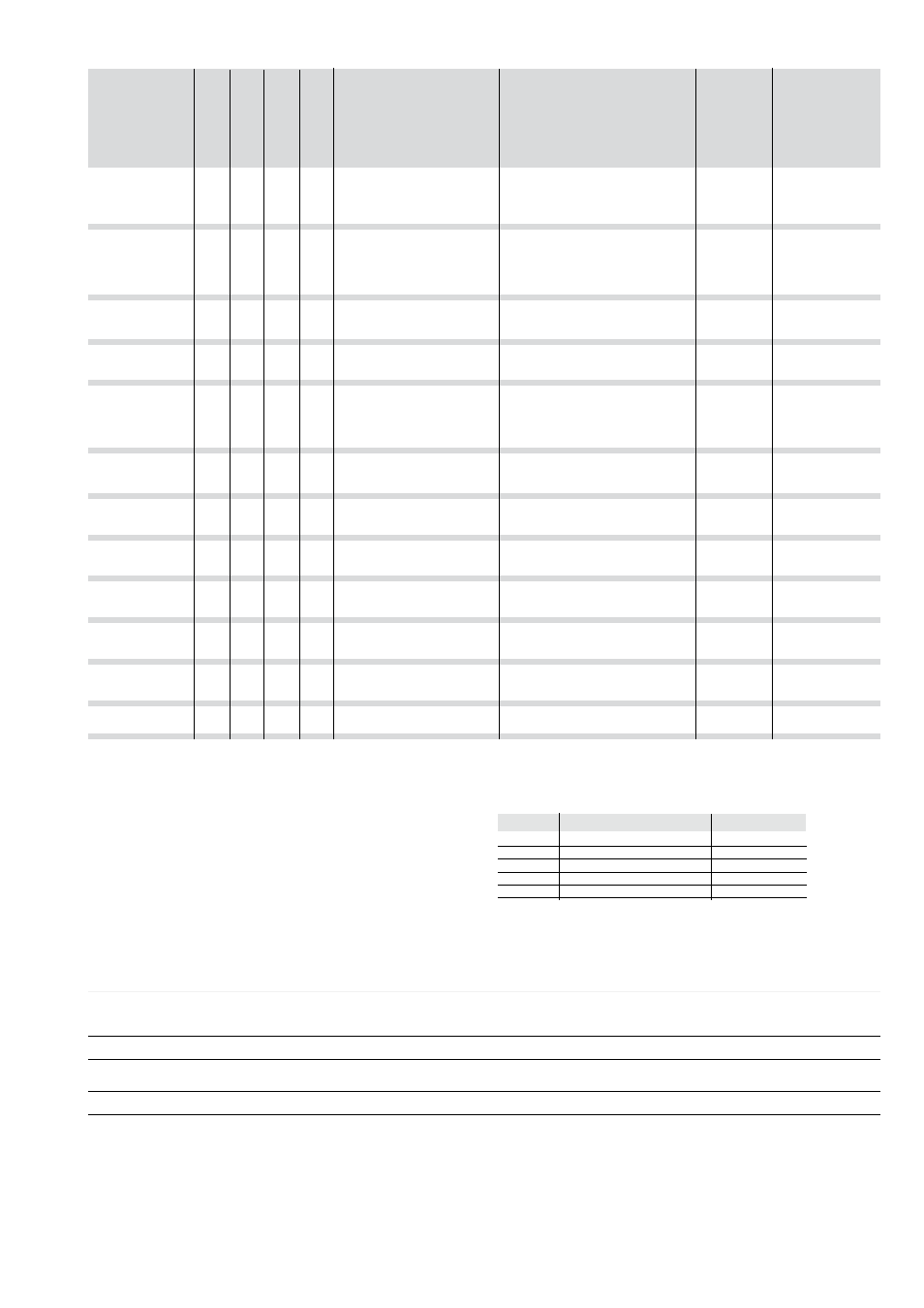
3.1.9.9
Summary table of the protection function settings for the LSIG-MM
Protection
Threshold
range
Time Tolerance
(2)
Time
range
Threshold
tolerance
(2)
Disabling
Disabling
TRIP only
Start-up threshold
Thermal memory
(1)
The minimum value of this trip is 1s regardless of the type of curve set (self-
protection)
(2)
These tolerances apply under the following conditions:
- self-powered relay at full power (without start-up)
- presence of auxiliary power supply
- two-phase or three-phase power supply
- preset trip time ≥ 100ms
(3)
Protection G is disabled for current values greater than 4In, where I4 < 0.4
In, greater than 6 In, where 0.5 In ≤ I4 < 0.8 In and greater than 8 In where I4
≥ 0.8 In.
For all cases not covered by the above assumptions, the following tolerance
values apply
Protections
Trip threshold
Trip time
L
Release between 1.05 and 1.25 x I1 ± 20%
S
± 10%
± 20%
I
± 15%
≤ 60ms
G
± 10%
± 20%
Others
± 20%
3.1.9.10
Table of measurements
Type of measurement
Tolerance
Range
%
Phase and neutral currents
0.3 ... 6 In
1.5
Internal ground fault current
0.3 ... 4 In
1.5
(internal source ground return)
Peak factor
0.3 ... 6 In
1.5