Wire recommendations – Rockwell Automation 20D PowerFlex 700 Installation Instructions - Frames 7…10 User Manual
Page 50
50
Rockwell Automation Publication 20B-IN014H-EN-P - June 2013
PowerFlex 700 Adjustable Frequency AC Drive – Frames 7…10
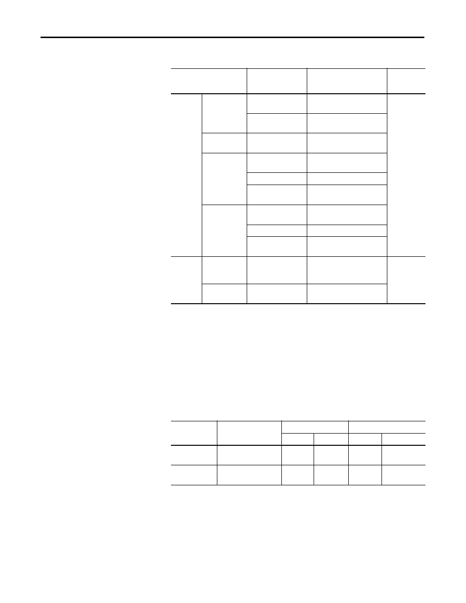
Wire Recommendations
I/O Terminal Block Specifications
Type
Wire Type(s)
Description
Min.
Insulation
Rating
Signal
(1) (2) (3)
(1) Control and signal wires must be separated from power wires by at least 0.3 meters (1 foot).
(2) If the wires are short and contained within a cabinet which has no sensitive circuits, the use of shielded wire may not be necessary,
but is always recommended.
(3) I/O terminals labeled “(–)” or “Common” are not referenced to earth ground and are designed to greatly reduce common mode
interference. Grounding these terminals can cause signal noise.
Standard Analog
I/O
Belden 8760/9460
(or equivalent)
0.750 mm
2
(18AWG), twisted pair,
100% shield with drain.
300V,
75…90 °C
(167…194 °F)
Belden 8770
(or equivalent)
0.750 mm
2
(18AWG), 3 conductor,
shielded for remote pot only.
Encoder/Pulse I/O
<30 m (100 ft.)
Combined:
Belden 9730
(4)
(4) 9730 is 3 individually shielded pairs (2 channel + power). If 3 channel is required, use 9728.
0.196 mm
2
(24AWG), individually
shielded
Encoder/Pulse I/O
30 to 152 m
(100 to 500 ft.)
Signal:
Belden 9730/9728
0.196 mm
2
(24AWG), individually
shielded
Power: Belden 8790
(5)
(5) 8790 is 1 shielded pair.
0.750 mm
2
(18AWG)
Combined:
Belden 9892
(6)
(6) 9892 is 3 individually shielded pairs (3 channel) + 1 shielded pair for power.
0.330 mm
2
(22AWG) or 0.500 mm
2
(20AWG)
Encoder/Pulse I/O
152 to 259 m
(500 to 850 ft.)
Signal:
Belden 9730/9728
0.196 mm
2
(24AWG), individually
shielded
Power: Belden 8790
0.750 mm
2
(18AWG)
Combined:
Belden 9773/9774
(7)
(7) 9773 is 3 individually shielded pairs (2 channel + power). If 3 channel is required, use 9774.
0.750 mm
2
(18AWG), individually
shielded
Digital I/O
Shielded
Multi-conductor shielded
cable such as Belden
8770 (or equivalent)
0.750 mm
2
(18AWG), 3 conductor,
shielded.
300V,
60 °C (140 °F)
Unshielded
Per US NEC or applicable
national or local code
–
Name
Description
Wire Size Range
(1)
(1) Maximum/minimum that the terminal block accepts - these are not recommendations.
Torque
Maximum
Minimum
Maximum
Recommended
I/O Terminal Block
Signal & control
connections
4.0 mm
2
(12 AWG)
0.049 mm
2
(30 AWG)
0.6 N•m
(5.3 lb•in)
0.6 N•m
(5.3 lb•in)
Encoder Terminal
Block
Encoder power & signal
connections
0.75 mm
2
(18 AWG)
0.196 mm
2
(24 AWG)
0.6 N•m
(5.3 lb•in)
0.6 N•m
(5.3 lb•in)