Environment, Minimum mounting clearances & heat dissipation, Removing the frame 7 cover – Rockwell Automation 20D PowerFlex 700 Installation Instructions - Frames 7…10 User Manual
Page 14: 14 minimum mounting clearances & heat dissipation, 14 removing the frame 7 cover
14
Rockwell Automation Publication 20B-IN014H-EN-P - June 2013
PowerFlex 700 Adjustable Frequency AC Drive – Frames 7…10
Environment
Operating Temperatures
PowerFlex 700 drives are designed to operate at 0…40 °C ambient. To operate the
drive in installations between 41…50 °C, see
and refer to pages
through
for exceptions.
Table 2 - Acceptable Surrounding Air Temperature & Required Actions
Minimum Mounting Clearances & Heat Dissipation
The drive must be mounted with sufficient space at the top, sides, and front of the
cabinet to allow for proper heat dissipation.
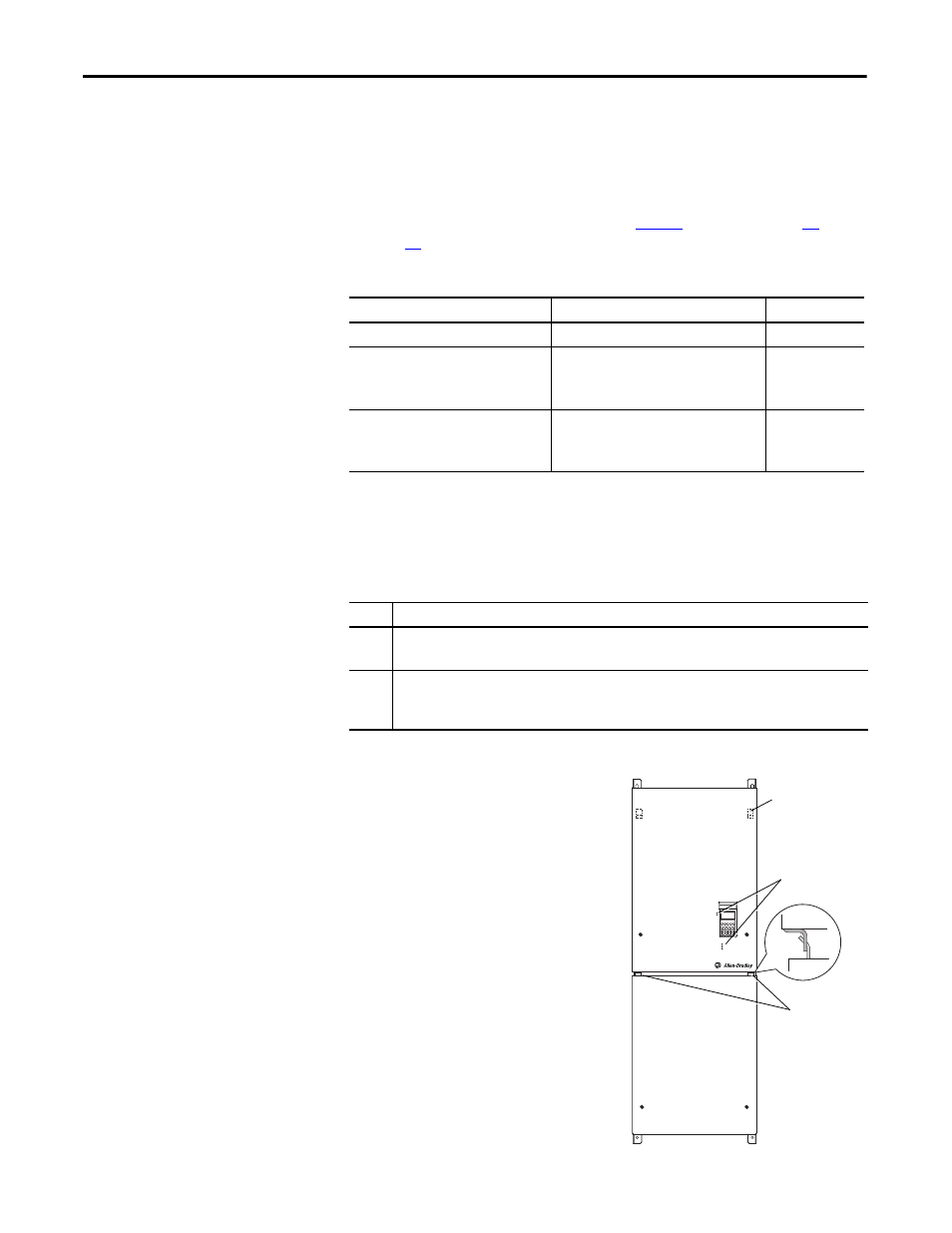
Removing the Frame 7 Cover
1.
Loosen lower panel screws and pull
the bottom edge out.
2.
Tilt panel sufficiently to remove
Hinge Tabs from the upper panel.
Remove panel and set aside.
3.
Loosen upper panel screws and pull
bottom edge out slightly.
4.
Slide panel down until Locating
Tabs clear chassis. Remove panel
and set aside.
5.
Replace panels in reverse order.
Carefully align tabs and light pipes.
Enclosure Rating
Temperature Range
Drive
IP20, NEMA/UL Type 1
0…40 °C (0…104 °F)
Frames 7…10
IP00, NEMA/UL Type Open/Flange Mount
Front: IP00, NEMA/UL Type Open
Back/Heat Sink: IP54, NEMA12
0…65 °C (0…149 °F) Control Board
0…40 °C (0…104 °F) Heat Sink Entry Air
Frames 7…10
Roll In
Front: IP00, NEMA/UL Type Open
Back/Heat Sink: IP54, NEMA12
0…65 °C (0…149 °F) Control Board
0…40 °C (0…104 °F) Heat Sink Entry Air
Frames 8…9
Frame
Recommendations
7
Minimum of 152 mm (6.0 in.) at the top and bottom of the enclosure and 102 mm (4.0 in.) on the sides.
Flange Mount - Minimum of 152 mm (6.0 in.) at the back of the enclosure (flange mount surface to wall).
8…10
Minimum of 152 mm (6.0 in.) at the top of the enclosure. Additionally, allow a minimum of 102 mm (4.0 in.)
on each side OR 152 mm (6.0 in.) in the back.
Flange Mount - Minimum of 102 mm (4.0 in.) on each side.
PORT
POWER
STS
NET A
NET B
MOD
Locating Tabs
(backside of panel)
Hinge Tabs
Light Pipes