Step 4: i/o wiring – Rockwell Automation 20D PowerFlex 700 Installation Instructions - Frames 7…10 User Manual
Page 49
Rockwell Automation Publication 20B-IN014H-EN-P - June 2013
49
PowerFlex 700 Adjustable Frequency AC Drive – Frames 7…10
Step 4: I/O Wiring
Important points to remember about I/O wiring:
•
Use Copper wire only. Wire gauge requirements and recommendations are
based on 75 degrees C. Do not reduce wire gauge when by using higher
temperature wire.
•
Wire with an insulation rating of 600V or greater is recommended.
•
Separate control and signal wires from power wires by at least 0.3 meters (1
foot).
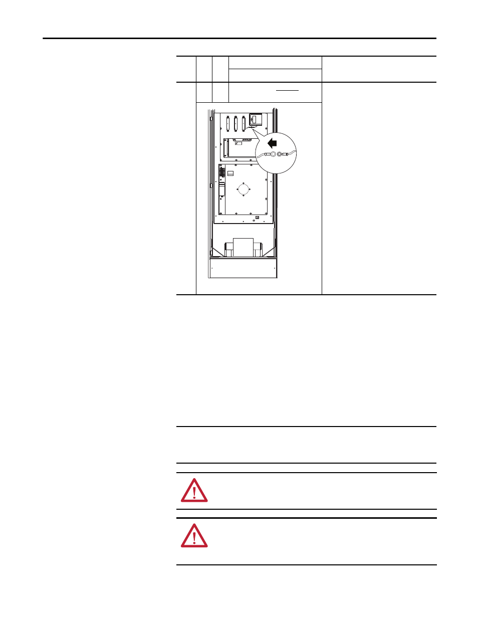
10
All
All
A green/yellow wire connected to
chassis
Solid Ground
Connect the green/yellow MOV jumper wire to the
chassis.
Non-Solid Ground
Remove the green/yellow MOV jumper wire from
the chassis. Insulate/secure the wire to guard
against unintentional contact with the chassis or
components.
(1) AC input drives only. MOV’s do not exist on DC input drives.
(2) Frame 7…10 drives do not have common mode capacitors.
Fram
e
Vo
lt
ag
e
Co
de
Curr
ent
Ra
ti
n
g Factory Default Jumper Settings
Power Source Type
MOV
(1) (2)
120
IN1
120
IN2
3
4
5
6
TB10
8 AMPERES RMS
MAXIMUM
GND
RISK OF SHOCK
REPLACE AFTER
SERVICING
!
DANGER
MOV
Jumper Wire
Converter Section
IMPORTANT
I/O terminals labeled “(–)” or “Common” are not referenced to earth ground
and are designed to greatly reduce common mode interference. Grounding
these terminals can cause signal noise.
ATTENTION: Configuring an analog input for 0…20 mA operation and driving
it from a voltage source could cause component damage. Verify proper
configuration prior to applying input signals.
ATTENTION: Hazard of personal injury or equipment damage exists when
using bipolar input sources. Noise and drift in sensitive input circuits can cause
unpredictable changes in motor speed and direction. Use speed command
parameters to help reduce input source sensitivity.