Bryant DURAPAC 551B User Manual
Page 28
28
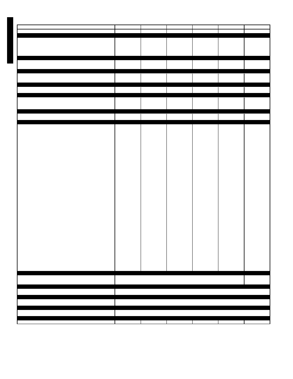
PHYSICAL DATA — 558F090-150
LEGEND
*Evaporator coil fin material/condenser coil fin material. Contact your local representative for
details about coated fins.
†Weight of 14-in. roof curb.
NOTES:
1. The 558F036-150 units have a loss-of-charge switch located in the liquid line.
2. High-static motor not available on size 150 units.
UNIT SIZE 558F
090
091
102
120
121
150
NOMINAL CAPACITY (tons)
7
1
/
2
7
1
/
2
8
1
/
2
10
12
1
/
2
OPERATING WEIGHT (lb)
Unit
Al/Al*
755
755
760
915
915
930
Al/Cu*
766
766
776
937
937
957
Cu/Cu*
778
778
787
960
960
980
EconoMi$er
62
62
62
62
62
62
Roof Curb†
143
143
143
143
143
143
COMPRESSOR
Reciprocating
Reciprocating
Reciprocating
Reciprocating
Reciprocating
Scroll
Quantity
2
2
2
2
1
2
No. Cylinders (per circuit)
2
2
2
2
2
2
Oil (oz)
42 ea
42 ea
65 ea
54 ea
50
54 ea
REFRIGERANT TYPE
R-22
Operating Charge (lb-oz)
Circuit 1
4-13
7-10
6-14
7- 3
7- 3
8-10
Circuit 2
4-14
8- 2
9- 2
7-13
7-13
8- 6
CONDENSER COIL
Enhanced Copper Tubes, Aluminum Lanced Fins
Rows...Fins/in.
1...17
1...17
2...17
2...17
2...17
2...17
Total Face Area (sq ft)
20.50
20.50
18.00
20.47
20.47
25.00
CONDENSER FAN
Propeller Type
Nominal Cfm
6400
6400
6400
7000
7000
7000
Quantity...Diameter (in.)
2...22
2...22
2...22
2...22
2...22
2...22
Motor Hp...Rpm
1
/
4
...1100
1
/
4
...1100
1
/
4
...1100
1
/
4
...1100
1
/
4
...1100
1
/
4
...1100
Watts Input (Total)
600
600
600
600
600
600
EVAPORATOR COIL
Enhanced Copper Tubes, Aluminum Double-Wavy Fins, Acutrol™ Metering Device
Rows...Fins/in.
3...15
3...15
3...15
3...15
3...15
4...15
Total Face Area (sq ft)
8.0
8.0
8.0
10.0
10.0
11.1
EVAPORATOR FAN
Centrifugal Type
Quantity...Size (in.)
Std
1...15 x 15
1...15 x 15
1...15 x 15
1...15 x 15
1...15 x 15
1...15 x 15
Alt
1...15 x 15
1...15 x 15
—
1...15 x 15
1...15 x 15
1...15 x 15
High-Static
1...15 x 15
1...15 x 15
1...15 x 15
1...15 x 15
1...15 x 15
—
Type Drive
Std
Belt
Belt
Belt
Belt
Belt
Belt
Alt
Belt
Belt
—
Belt
Belt
Belt
High-Static
Belt
Belt
Belt
Belt
Belt
—
Nominal Cfm
3000
3000
3100
4000
4000
5000
Maximum Continuous Bhp
Std
2.40
2.40
2.40
2.40
2.40
3.70
Alt
2.40
2.40
—
2.90
2.90
5.25
High-Static
3.70
3.70
3.70
5.25
5.25
—
Motor Frame Size
Std
56
56
56
56
56
56
Alt
56
56
—
56
56
56
High-Static
56
56
56
56
56
—
Nominal Rpm High/Low
Std
—
—
—
—
—
—
Alt
—
—
—
—
—
—
High-Static
1725
1725
1725
1725
1725
1725
Fan Rpm Range
Std
590- 840
590- 840
685- 935
685- 935
685- 935
860-1080
Alt
685- 935
685- 935
—
835-1085
835-1085
900-1260
High-Static
860-1080
860-1080
860-1080
830-1130
830-1130
—
Motor Bearing Type
Ball
Ball
Ball
Ball
Ball
Ball
Maximum Allowable Rpm
2100
2100
2100
2100
2100
2100
Motor Pulley Pitch Diameter Min/Max (in.)
Std
2.4/3.4
2.4/3.4
2.8/3.8
2.8/3.8
2.8/3.8
4.0/5.0
Alt
2.8/3.8
2.8/3.8
—
3.4/4.4
3.4/4.4
3.1/4.1
High-Static
4.0/5.0
4.0/5.0
4.0/5.0
2.8/3.8
2.8/3.8
—
Nominal Motor Shaft Diameter (in.)
Std
5
/
8
5
/
8
5
/
8
5
/
8
5
/
8
7
/
8
Alt
5
/
8
5
/
8
—
7
/
8
7
/
8
7
/
8
High-Static
7
/
8
7
/
8
7
/
8
7
/
8
7
/
8
—
Fan Pulley Pitch Diameter (in.)
Std
7.0
7.0
7.0
7.0
7.0
8.0
Alt
7.0
7.0
—
7.0
7.0
5.9
High-Static
8.0
8.0
8.0
5.8
5.8
—
Belt, Quantity...Type...Length (in.)
Std
1...A...49
1...A...49
1...A...49
1...A...49
1...A...49
1...A...52
Alt
1...A...49
1...A...49
—
1...A...49
1...A...49
1...BX...46
High-Static
1...A...55
1...A...55
1...A...55
1...BX...46
1...BX...46
—
Pulley Center Line Distance (in.)
Std
16.75-19.25
16.75-19.25
16.75-19.25
15.85-17.50
15.85-17.50
15.85-17.50
Alt
15.75-19.25
15.75-19.25
—
15.85-17.50
15.85-17.50
15.85-17.50
High-Static
15.75-19.25
15.75-19.25
16.75-19.25
15.85-17.50
15.85-17.50
—
Speed Change per Full Turn of
Movable Pulley Flange (rpm)
Std
50
50
50
50
50
44
Alt
50
50
—
50
50
50
High-Static
60
60
60
60
60
—
Movable Pulley Maximum Full Turns
From Closed Position
Std
5
5
5
5
5
5
Alt
5
5
—
5
5
6
High-Static
5
5
5
6
6
—
Factory Setting
Std
5
5
5
5
5
5
Alt
5
5
—
5
5
5
High-Static
5
5
5
5
5
—
Factory Speed Setting (rpm)
Std
590
590
685
685
685
860
Alt
685
685
—
835
835
960
High-Static
860
860
860
887
887
—
Fan Shaft Diameter at Pulley (in.)
1
1
1
1
1
1
HIGH-PRESSURE SWITCH (psig)
Standard Compressor Internal Relief (Differential)
450 ± 50
500
±
50
Cutout
428
428
Reset (Auto.)
320
320
LOW-PRESSURE SWITCH (psig)
Cutout
7 ± 3
Reset (Auto.)
22 ± 7
FREEZE-PROTECTION THERMOSTAT (F)
Opens
30 ± 5
Closes
45 ± 5
OUTDOOR-AIR INLET SCREENS
Cleanable
Quantity...Size (in.)
1...20 x 25 x 1
1...16 x 25 x 1
RETURN-AIR FILTERS
Throwaway
Quantity...Size (in.)
4...16 x 20 x 2
4...16 x 20 x 2
4...16 x 20 x 2
4...20 x 20 x 2
4...20 x 20 x 2
4...20 x 20 x 2
Al
— Aluminum
Bhp — Brake Horsepower
Cu
— Copper
0TF
Q
00
4-
01
2
55
8F0
36-
15
0