Bryant DURAPAC 551B User Manual
Page 17
17
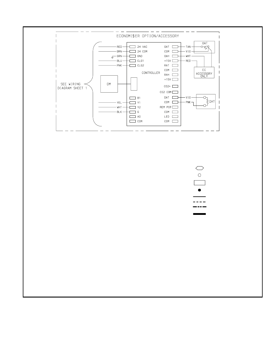
TYPICAL WIRING SCHEMATIC (Sizes 155-300)
LEGEND
AHA
— Adjustable Heat Anticipator
AWG
— American Wire Gage
BRK W/AT — Breaks with Amp Turns
C
— Contactor, Compressor
CAP
— Capacitor
CB
— Circuit Breaker
CC
— Cooling Compensator
CH
— Crankcase Heater
CLO
— Compressor Lockout
COMP
— Compressor Motor
CR
— Control Relay
CT
— Current Transformer
DAT
— Discharge Air Thermistor
DM
— Damper Motor
DU
— Dummy Terminal
EC
— Enthalpy Control
EQUIP
— Equipment
ER
— EconoMi$er Relay
EPS
— Emergency Power Supply
(9 volt)
FL
— Fuse Link
FLA
— Full Load Amps
FPT
— Freeze Protection Thermostat
FSS — Filter Status Switch
FU
— Fuse
GND — Ground
HC
— Heater Contactor
HPS — High-Pressure Switch
HTR — Heater
IFC
— Indoor-Fan Contactor
IFCB — Indoor-Fan Circuit Breaker
IFM
— Indoor-Fan Motor
IFR
— Indoor-Fan Relay
L
— Light
LOR — Lockout Relay
LPS — Low-Pressure Switch
LS
— Limit Switch
LSM — Limit Switch (Manual Reset)
OAT — Outdoor-Air Thermostat
OFC — Outdoor-Fan Contactor
OFM — Outdoor-Fan Motor
OP
— Overcurrent Protection
PL
— Plug Assembly
PRI
— Primary
QT
— Quadruple Terminal
SAT — Supply Air Thermostat
SW
— Switch
TB
— Terminal Block
TC
— Thermostat Cooling
TH
— Thermostat Heating
TRAN — Transformer
Terminal (Marked)
Terminal (Unmarked)
Terminal Block
Splice
Factory Wiring
Field Wiring
Option/Accessory Wiring
To indicate common potential
only; not to represent wiring.
NOTES:
1. Compressor and/or fan motor(s) thermally protected; 3-phase motors protected
against primary single-phasing conditions.
2. If any of the original wire furnished must be replaced, it must be replaced with
type 90° C wire or its equivalent.
3. Jumpers are omitted when unit is equipped with EconoMi$er.
5. IFCB must trip amps is equal to or less than 140% FLA.
6. The CLO locks out the compressor to prevent short cycling on compressor over-
load and safety devices. Before replacing CLO, check these devices.
7. Number(s) indicates the line location of used contacts. A bracket over (2) num-
bers signifies a single-pole, double-throw contact. An underlined number signi-
fies a normally closed contact. Plain (no line) number signifies a normally open
contact.