MacDon 873 Combine Adapter User Manual
Page 56
Form # 147069
Issue 09/06
54
Adapter Mounting Instructions
for Case AFX / New Holland CR & CX Combines
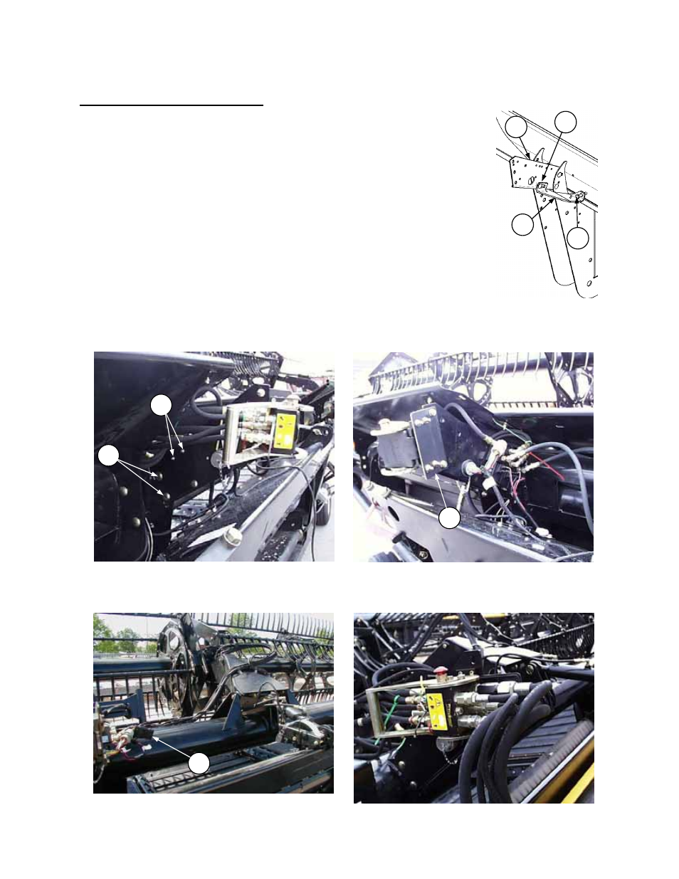
PREPARING THE 973/974 HEADER
1.
Attach the hydraulic/electrical completion package as follows:
• Mount the coupler bracket provided with the adapter to the inboard flange of the left
header leg with two 1/2 x 1 inch carriage bolts and flange nuts at (A). (For 963 Header,
coupler bracket bolts to a bracket welded to the header back tube near left side of
opening.)
• Attach brace (D) to coupler bracket (F) using 1/2 x 1 inch carriage bolt and flange nut
at (G). Ensure brace (D) is tight against backtube and bottom of coupler bracket.
Tighten bolt (E) and jam nut after tightening brace to coupler bracket. Bolt (E) should
be tight enough to ensure L/H leg of brace is tight against backtube.
• NOTE: If upper cross auger shielding is installed, install adapter bracket (C) and move
multi-link coupler onto this bracket as shown. This allows clearance to lock the multi-
link handle over-center.
• Match the coloured cable ties to connect the header hoses to the multi-link coupler:
Reel Drive – Yellow to Yellow and White to White.
Reel Lift – Black to Black
• Mount the Reel Fore-Aft/Header Tilt selector valve (if equipped) to the coupler
bracket with two 1/4 x 2-1/2 inch hex bolts and nuts at (B).
• Match the coloured cable ties to connect hoses for Reel Fore-Aft/Header Tilt – Red to Red and Green to Green,
on the multi link connector.
• A header recognition resistor (H) is supplied with the adapter. This plugs into the main harness with short adapter
provided, or into float optimizer sensor harness (if equipped), to send a recognition signal to the combine computer.
MULTI-LINK CONNECTED TO HEADER
FLOAT OPTIMIZER –
HEADER RECOGNITION RESISTOR
H
OUTBOARD VIEW
INBOARD VIEW
ATTACH REEL DRIVE MOUNTING PLATE TO HEADER L/H LEG
(SHOWN WITH UPPER CROSS AUGER SHIELDING PACKAGE INSTALLED)
C
A
B
D
E
G
F