Assembly, Preparing the adapter – MacDon 873 Combine Adapter User Manual
Page 48
Form # 147069
Issue 09/06
46
ASSEMBLY
Preparing the Adapter
POSITION THE RETRACTING TINE DRUM (continued)
IMPORTANT: To prevent damage to header side
drapers or adapter drum when dimension “X” (from
previous page) exceeds 10” (255 mm) on 972, 973 &
974 headers, or 9-1/2” (235 mm) on 963 headers,
float lockout pins must be located to prevent header
from floating fully up when float is engaged.
NOTE: Adapter leg must also be in position “B” when
RTD is this far forward, refer to page 39.
To find a safe position for float lockout pins for these
situations:
1. The normal “float engaged” position for handle (A)
is fully down as shown. In situations where float
must be limited to prevent damage, the handle
must be raised and pinned in a higher position.
2. To find this position, once header is attached,
shorten center link to minimum length and float
header up. For 974 Headers, set to maximum
“smile” position by lowering onto 5” (125 mm)
blocks at each end.
3. Raise handle (A) both sides, to hole (J) for
963/973/974 Headers or hole (K) for 972
Headers. This is the “header attach” position and
ensures no interference.
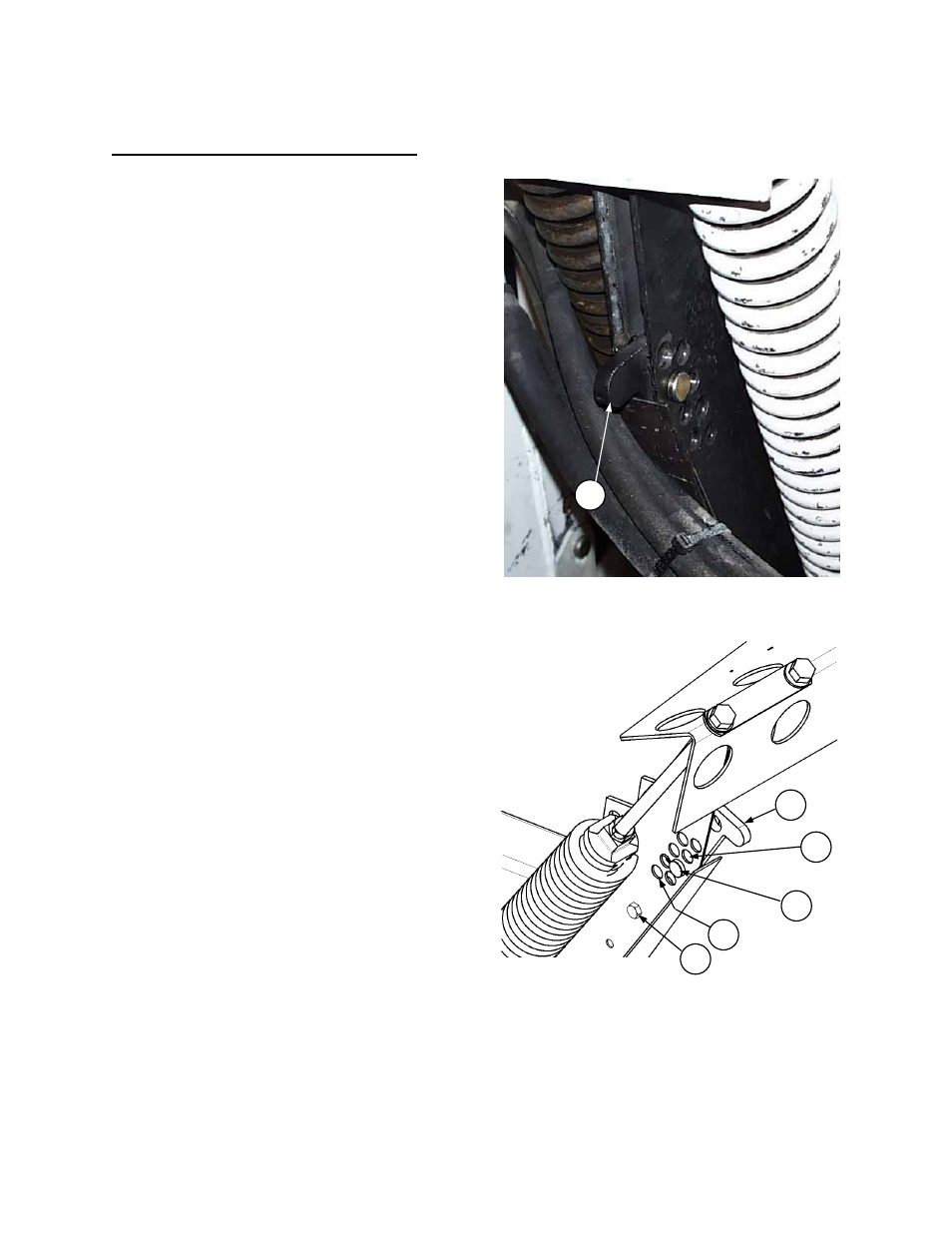
NOTE: For John Deere Contour Master combines
with 963 Harvest Headers, rest handle (A) on bolt
(B) and place pin in hole (L). Bolt (B) should be
located in lower hole for all other combines.
4. Starting from this position, lower handle one hole
at a time and turn drum by hand, checking for
interference.
5. When interference occurs, return to previous
higher position and make a mark on the float
frame at top of handle for future reference. Use
this position when operating the header.
A
LIMIT FLOAT BY RAISING “ENGAGED”
POSITION OF HANDLE
J
K
START FROM “HEADER ATTACH” POSITION
AND LOWER HANDLE TO FIND “FLOAT
LIMITED” OPERATING POSITION
L
A
B