MacDon 9352c SP User Manual
Page 92
Form # 147459
Issue 11/06 Web Rev_01
90
MAINTENANCE/SERVICE
Hydraulic System: Header & Reel Lift
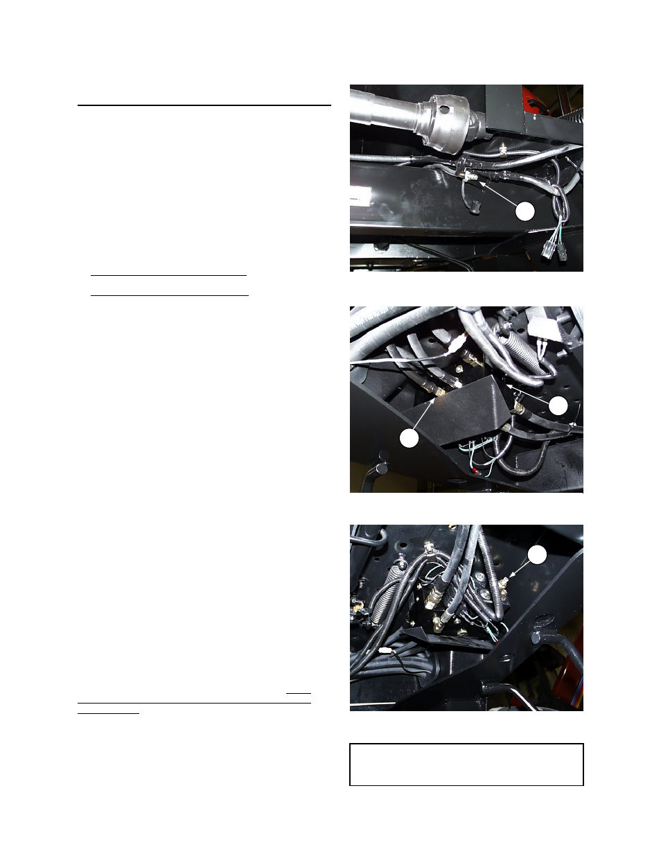
CYLINDER CONTROL VALVE RELIEF PRESSURE
Control valve (A), located under the R/H tractor
floorboard, directs hydraulic flow to the header lift
cylinders, reel lift cylinders and the cylinder used to
engage the clutch for the sickle drive.
The control valve relief pressure is pre-set to be
sufficient for all header sizes and options. Should lift
capacity problems develop, check and adjust cylinder
control valve relief pressure as follows:
1. Lower header and reel fully, stop engine and remove
key from ignition.
2. The same relief valve protects both header and reel
lift circuits. It is most convenient to check relief
pressure in the reel lift circuit.
For tractors with reel lift hydraulics, reel lift quick
coupler (B) is located at left-hand leg.
For tractors without reel lift hydraulics, the header lift
circuit may be tapped at Port "C" of the lift valve.
Remove hose (C) to access port.
3. Attach a 3000 psi (20 MPa) pressure gauge to a
hose that is long enough to allow pressure to be
read from the operator's seat. Attach hose to quick
coupler or valve (see step 2) and position gauge to
be visible from the seat.
4. Start engine and position throttle lever fully back
(low idle). When oil is warm (minimum 100° F (38°
C)), activate the lift control for the circuit you have
tapped (reel or header) and check gauge pressure
reading.
5. Pressure should be 2400 to 2650psi (16.5 to 18.2
MPa)
If not, proceed with adjustment:
EXCEPTION: 36’ 972 Header requires 2500 psi
(17.2 MPa).
6. Lower header and reel fully. Stop engine and remove
key.
7. To adjust relief setting:
• Loosen jam nut at relief valve (D).
• Turn the adjustment screw in 1/4 turn increments,
clockwise to increase relief pressure, counter-
clockwise to decrease.
NOTE: 1/4 turn = approx. 80 psi change
8. Repeat checking and adjustment until relief pressure
is correct, then tighten nut at (D).
IMPORTANT: If relief pressure does not increase after
adjusting the screw two or three times, check relief valve
as follows: Remove relief valve (D) from control valve
block. Check that no contaminant is preventing the
spring-loaded poppet from properly seating against the
valve
body. Clean as required, and reinstall valve. Reset
adjustment screw to original position before checking
relief pressure.
B
REEL LIFT QUICK COUPLER
C
A
CYLINDER CONTROL VALVE (FRONT VIEW)
D
CYLINDER CONTROL VALVE (REAR VIEW)
NOTE: For hydraulic schematics, see
“SCHEMATICS” section at back of this
book.