Electrical installation – Lenze EVF9338 User Manual
Page 89
Electrical installation
Motor connection
Wiring of motor temperature monitoring
l
89
EDKVF9338 DE/EN/FR 4.0
Characteristics of the connection for motor temperature monitoring:
Terminals T1, T2
Connection
l
PTC thermistor
– PTC thermistor with defined tripping temperature (acc. to DIN 44081 and
DIN 44082)
l
Thermal contact (NC contact)
– Thermostat as NC contact
Tripping point
l
Fixed (depending on the PTC/thermal contact)
l
PTC: R
J
>
1600
W
l
Configurable as warning or error (TRIP)
Notes
l
Monitoring is not active in the Lenze setting.
l
If you do not use a Lenze motor, we recommend the use of a PTC thermistor up
to 150°C.
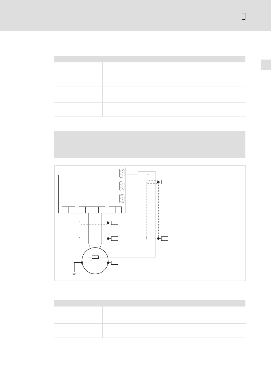
Motor with KTY thermal sensor
)
Note!
ƒ
We recommend to use Lenze system cables for wiring.
ƒ
For self−made cables only use cables with shielded cores twisted in pairs.
PE U V W
T1 T2
+UG -UG
PES
PES
PE
M
3~
PES
PES
KTY
X8/5
X8/8
PES
X8
X9
X10
9300vec121
Fig. 5−8
Connection of KTY thermal sensor at incremental encoder input X8
Characteristics of the connection for motor temperature monitoring:
Pins X8/5, X8/8 of incremental encoder input (X8)
Connection
Linear KTY thermal sensor
Tripping point
l
Warning: Adjustable
l
Error (TRIP): Fixed at 150 °C
Notes
l
Monitoring is not active in the Lenze setting.
l
The KTY thermal sensor is monitored with regard to interruption and short
circuit.