4 motor connection, Motor connection, Electrical installation – Lenze EVF9338 User Manual
Page 87: Stop
Electrical installation
Motor connection
Fan connection
l
87
EDKVF9338 DE/EN/FR 4.0
5.4
Motor connection
ƒ
To comply with the EMC regulations, Lenze recommends to use shielded motor
cables.
ƒ
Shield clamps are not included in the scope of supply.
(
Stop!
The user is responsible for sufficient strain relief!
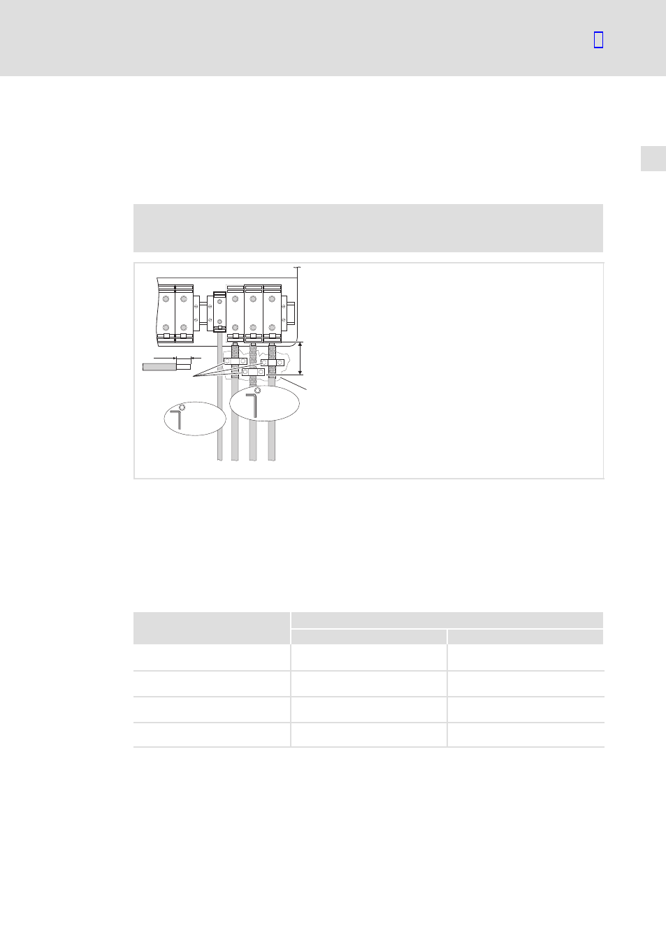
BR2
BR1
PE U
V
W
40 mm
PE
15-20 Nm
M6
133-176 lb-in
U, V, W
25-30 Nm
M8
221-264 lb-in
0
max.
300 mm
1
9300VEC005
Fig. 5−6
Motor connection example
BR1, BR2
The brake resistor can only be operated with the variants V060, V110, V270 and V300
For connection see the 9300 vector System Manual
0
Connect the motor cable shield with a surface as large as possible to the control
cabinet mounting plate by using the clamps.
1
Conductive surface
Ensure to have the poles right!
Do not exceed the maximum motor cable length!
Cable cross−sections for the motor connection
Type
Installation to EN 60204−1
U, V, W [mm
2
]
PE [mm
2
]
EVF9335−EV
EVF9335−EVVxxx
150
2 × 50
1)
95
EVF9336−EV
EVF9336−EVVxxx
150
2 × 50
1)
95
EVF9337−EV
EVF9337−EVVxxx
150
2 × 50
1)
95
EVF9338−EV
EVF9338−EVVxxx
240
2 × 95
1)
150
1)
Multiple conductor; both conductors must have the same cross−section
Observe the national and regional legislation