Electrical installation – Lenze EVF9338 User Manual
Page 81
Electrical installation
Installation according to EMC (installation of a CE−typical drive system)
l
81
EDKVF9338 DE/EN/FR 4.0
EVF9335-EV …
EVF9338-EV
K10
L1
L2
L3
N
PE
F1 … F3
PES
PES
PES PES
PES
PES
PES
PES
3
7
4
63
2
62
1
7
X6
28
E1
E2
E3
E5
E4
ST1
ST2
39
A1
A3
A2
A4
59
X5
33
34
K32
K31
IN2
IN3
IN4
IN1
X11
PE U V W
T1 T2
BR1BR2+UG -UG
S1
K10
K10
S2
PE
101 102 103 104
L1 L2 L3
DC 24 V
Z1
+
–
PE
PE
M
3~
M
3~
KTY
X8/5
X8/8
PE
J>
PES
PES
PES
PES
PES
PES
PES
PES
PES
PE
Z2
JRB
RB
RB2
T2
T1
RB1
PE
PE
9300VEC007
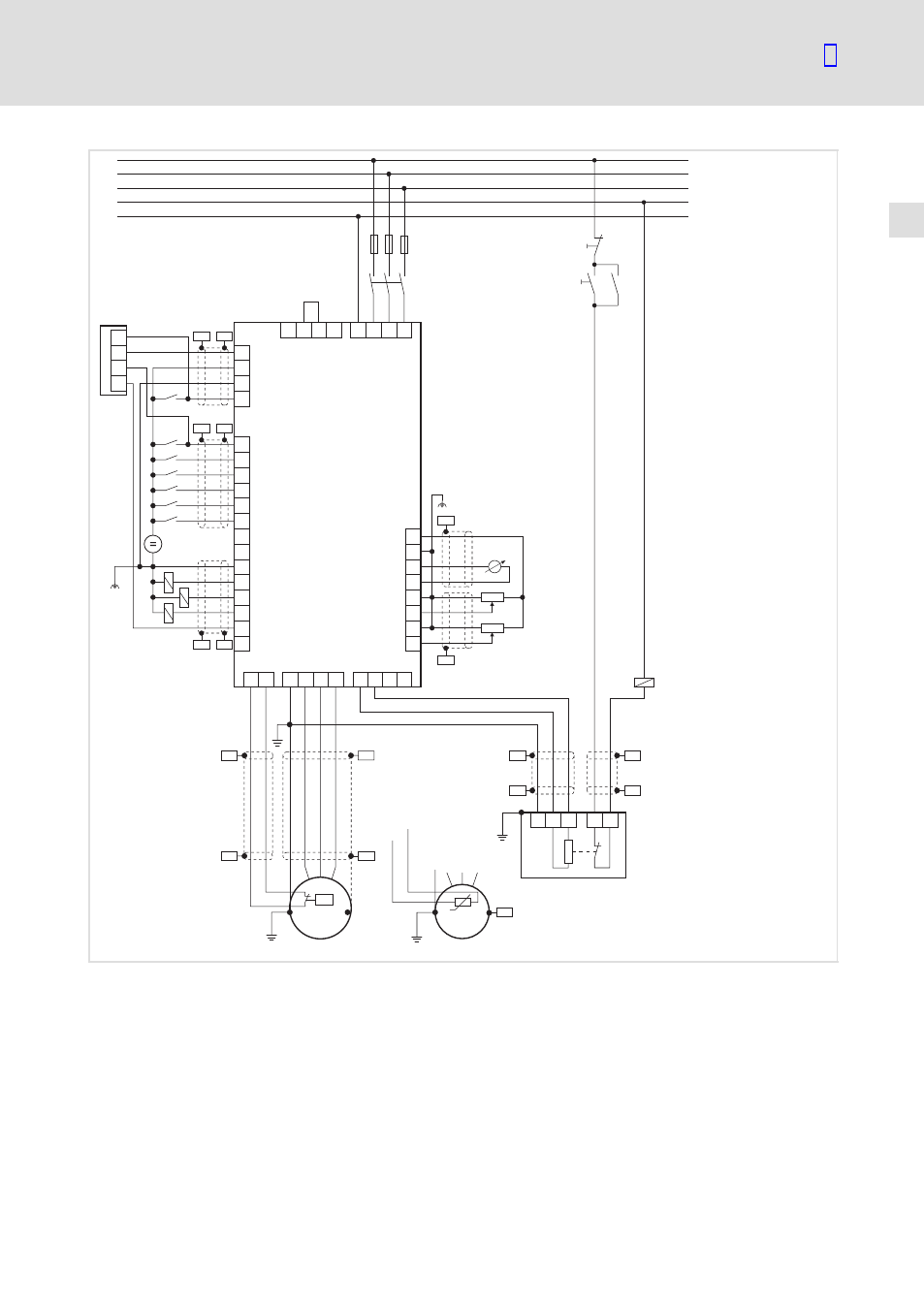
Fig. 5−1
Example for wiring in accordance with EMC regulations
F1 ... F3
Fuses
K10
Mains contactor
Z1
Programmable logic controller (PLC)
Z2
Brake resistor
S1
Mains contactor on
S2
Mains contactor off
+U
G
, −U
G
DC−bus connection
PES
HF shield termination through large−surface connection to PE
This manual is related to the following products: