2 connection to the dc bus (+ug, -ug), Connection to the dc bus (+ug, −ug), Electrical installation – Lenze EVF9338 User Manual
Page 84: 2 connection to the dc bus (+u
Electrical installation
Supply and fan connection at the controller for a mains voltage of 400 V/500V
Connection to the DC bus (+UG, −UG)
l
84
EDKVF9338 DE/EN/FR 4.0
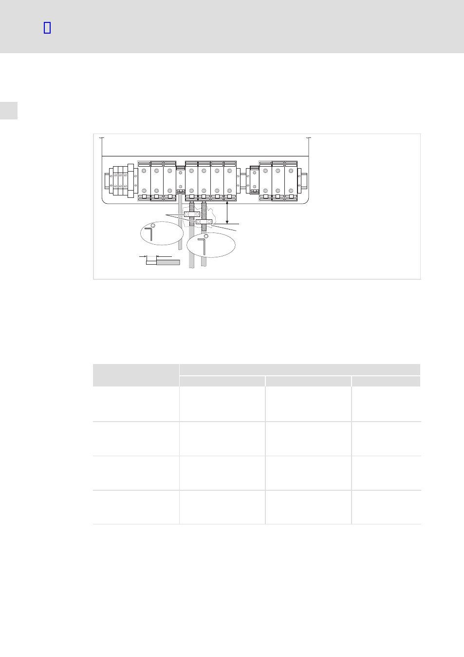
5.3.2
Connection to the DC bus (+U
G
, −U
G
)
ƒ
For compliance with EMC requirements, Lenze recommends to use shielded DC−bus
cables.
ƒ
Shield clamps are not included in the scope of supply.
BR2
BR1
+UG -UG
PE U
V
W
L1
101 102 103 104
L2 L3 PE
40 mm
PE
15-20 Nm
M6
133-176 lb-in
+U
G
-U
G
25-30 Nm
M8
221-264 lb-in
max.
300 mm
1
0
9300VEC074
Fig. 5−4
Connection example to +U
G
and −U
G
BR1, BR2
Brake resistors can only be operated with variants V270 and V300
For connection see the 9300 vector System Manual
0
Connect the DC−bus cable shield to the conductive control cabinet mounting plate with
a contact surface as large as possible by using the shield clamps.
1
Conductive surface
Ensure to have the poles right!
Fuses and cable cross−sections for DC−bus connection
Type
Installation to EN 60204−1
Fuse
2)
+U
G
, −U
G
[mm
2
]
PE [mm
2
]
EVF9335−EVV210
EVF9335−EVV240
EVF9335−EVV270
EVF9335−EVV300
315A
150
2 × 50
1)
95
EVF9336−EVV210
EVF9336−EVV240
EVF9336−EVV270
EVF9336−EVV300
350 A
150
2 × 50
1)
95
EVF9337−EVV210
EVF9337−EVV240
EVF9337−EVV270
EVF9337−EVV300
400 A
240
2 × 95
1)
95
EVF9338−EVV210
EVF9338−EVV240
EVF9338−EVV270
EVF9338−EVV300
500 A
240
2 × 95
1)
150
1)
Multiple conductor; both conductors must have the same cross−section
2)
Only use fuses of the gRL utilisation category
Observe the national and regional legislation