4 technical data, 1 general data and operating conditions, Technical data – Lenze E94AYCIB User Manual
Page 15: General data and operating conditions, 4technical data
Lenze · E94AYCIB communication module (INTERBUS) · Communication Manual · DMS 4.0 EN · 02/2014 · TD17
15
4
Technical data
4.1
General data and operating conditions
_ _ _ _ _ _ _ _ _ _ _ _ _ _ _ _ _ _ _ _ _ _ _ _ _ _ _ _ _ _ _ _ _ _ _ _ _ _ _ _ _ _ _ _ _ _ _ _ _ _ _ _ _ _ _ _ _ _ _ _ _ _ _ _
4
Technical data
4.1
General data and operating conditions
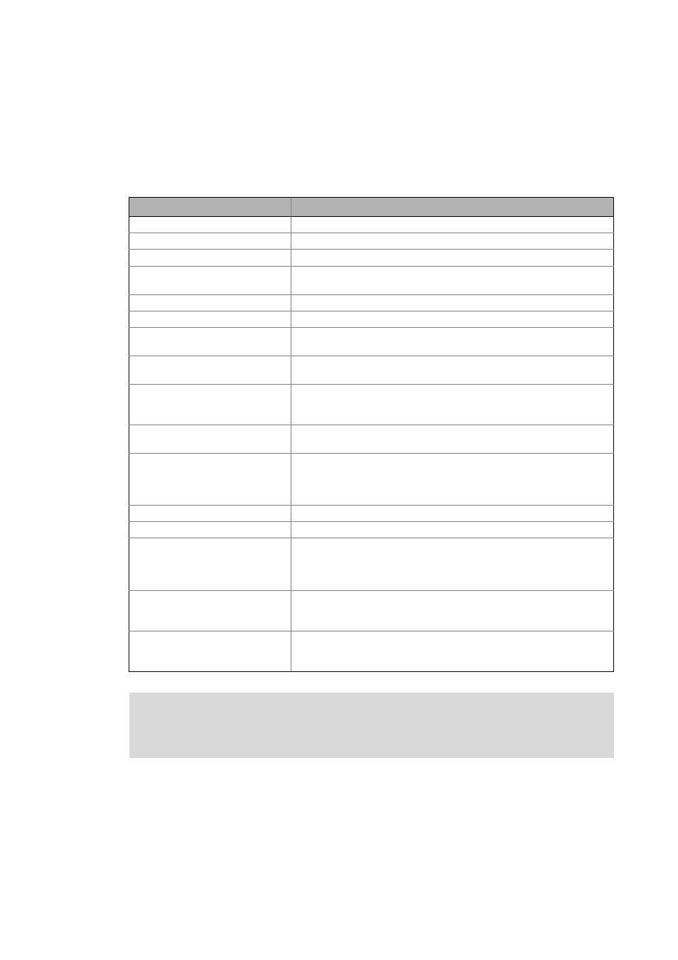
Range
Values
Order designation
E94AYCIB
Communication profile
INTERBUS
Communication medium
RS485
Interface for communication
• Input (IN): 9-pole Sub-D plug
• Output (OUT): 9-pole Sub-D socket
Network topology
Ring
Type of node
Slave
Number of nodes
• 1 master
• 512 slaves
Baud rate
500 kbps or 2 Mbps
(can be set via DIP switch or code)
Max. cable length
• 400 m at 500 kbps
• 150 m at 2 Mbps
(between the single INTERBUS nodes)
Process data words
0 ... 10 words (16 bits/word)
(can be set via DIP switch or code)
Parameter data words
0, 1, 2, 4 words (16 bits/word)
(can be set via DIP switch or code)
The parameter data is transmitted in accordance with the Peripherials
Communication Protocol (PCP).
Max. number of data words
10 words (process data word + parameter data words), 16 bits/word
Max. PDU length
64 bytes
Device identification (module ID)
• 3 = 0x03 (0 parameter data words)
• 227 = 0xE3 (1 parameter data words)
• 224 = 0xE0 (2 parameter data words)
• 225 = 0xE1 (4 parameter data words)
Voltage supply
External supply via separate power supply unit
+: U = 24 V DC (+/- 10 %), I
max
= 180 mA
- : Reference potential for external voltage supply
Conformities, approvals
• CE
• UL
(see also hardware manual)
Servo Drives 9400 hardware manual
Here you can find the ambient conditions and information on the electromagnetic
compatibility (EMC) which also apply to the communication module.