Troubleshooting and diagnostics – Lenze ESV SMV frequency inverter User Manual
Page 62
60
Lenze SMVector 13465100 EDBSV01 EN v18
Troubleshooting and Diagnostics
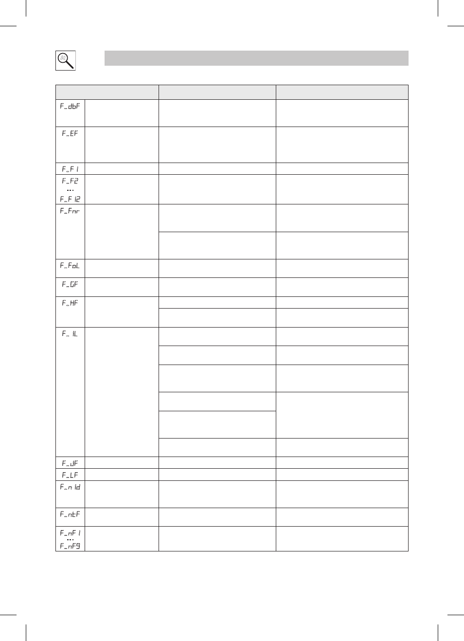
Fault
Cause
Remedy
(1)
f.dbF
Dynamic Braking fault
Dynamic braking resistors are overheating • Increase active decel time
(P105, P126, P127).
• Check mains voltage and P107
f.EF
External fault
• P121…P124 = 21 and that digital input
has been opened.
• P121…P124 = 22 and that digital input
has been closed.
• Correct the external fault condition
• Make sure digital input is set properly for NC
or NO circuit
f.F1
EPM fault
EPM missing or defective
Power down and replace EPM
f.F2
…
f.F12
Internal faults
Contact factory technical support
f.Fnr
Control Configuration Fault The drive is setup for REMOTE KEYPAD
control (P100=2 or 5) but is not setup to
communicate with a remote keypad
Set P400 = 1, or P600 = 1
The drive is setup for NETWORK ONLY
control (P100=3) but is not setup for
network communications
Set P400 or P600 to a valid network
communications protocol selection
f.FoL
TB25 (4-20 mA signal)
Threshold fault
4-20 mA signal (at TB-25) drops below the
value set in P164.
• Check signal/signal wire
• Refer to parameters P163 and P164.
f.GF
OEM Defaults data fault
Drive is powered up with P199 =1 and
OEM settings in the EPM are not valid.
Install an EPM containing valid OEM Defaults
data or change P199 to 0.
f.HF
High DC Bus Voltage fault
Mains voltage is too high
Check mains voltage and P107
Decel time is too short, or too much regen
from motor
Increase active decel time (P105, P126, P127)
or install Dynamic Braking option
f.1L
Digital Input
Configuration fault (P121...
P124)
More than one digital input set for the same
function
Each setting can only be used once (except
settings 0 and 3)
Only one digital input configured for MOP
function (Up, Down)
One input must be set to MOP Up, another must
be set to MOP Down
PID mode is entered with setpoint
reference and feedback source set to the
same analog signal
Change PID setpoint reference (P121…P124) or
feedback source (P201).
One of the digital inputs (P121…P124) is
set to 10 and another is set to 11…14.
Reconfigure digital inputs
One of the digital inputs (P121…P124)
is set to 11 or 12 and another is set to
13 or 14.
PID enabled in Vector Torque mode (P200
= 1 or 2 and P300 = 5)
PID cannot be used in Vector Torque mode
f.JF
Remote keypad fault
Remote keypad disconnected
Check remote keypad connections
f.LF
Low DC Bus Voltage fault Mains voltage too low
Check mains voltage
f.n1d
No Motor ID fault
An attempt was made to start the drive
in Vector or Enhanced V/Hz mode prior to
performing the Motor Auto-calibration
Refer to parameters P300…P399 for Drive Mode
setup and calibration.
f.ntF
Module communication
fault
Communication failure between drive and
Network Module.
Check module connections
f.nF1
…
f.nF9
Network Faults
Refer to the module documentation. for
Causes and Remedies.