Commissioning, 4 pid parameters – Lenze ESV SMV frequency inverter User Manual
Page 41
Lenze SMVector 13465100 EDBSV01 EN v18
39
Commissioning
Code
Possible Settings
IMPORTANT
No.
Name
Default Selection
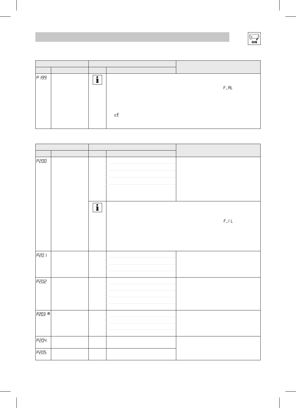
p199
Program Selection
NOTE 4
Resetting to 50 and 60 Hz default settings will set the Assertion Level (P120) to “2” (High).
P120 may need to be reset for the digital input devices being used. An F.AL fault may occur
if P120 and the Assertion switch are not set identically.
NOTE 5
If an EPM that contains data from a previous compatible software version is installed:
• The drive will operate according to the previous data, but parameters cannot be changed
(cE will be displayed if attempted)
• To update the EPM to the current software version, set P199 = 5. The parameters can now
be changed but the EPM is incompatible with previous software revisions.
4.5.4
PID Parameters
Code
Possible Settings
IMPORTANT
No.
Name
Default Selection
P200
PID Mode
0
0 Disabled
• Normal-acting: As feedback increases, motor
speed decreases
• Reverse-acting: As feedback increases, motor
speed increases
• PID mode is disabled in Vector Torque mode
(P300 = 5)
• Selections 3, 4: If P112=1, PID controller output
sets the speed, (range -max freq to +max freq)
1 Normal-acting
2 Reverse-acting
3 Normal-acting, Bi-directional
4 Reverse-acting, Bi-directional
NOTE
To activate PID mode, one of the TB-13 inputs (P121...P124) must be used to select the
Auto Reference that matches the desired PID setpoint reference. If the selected PID setpoint
reference uses the same analog signal as the PID feedback (P201), an F.IL fault will occur.
Example: The desired PID setpoint reference is the keypad (p and q). Set TB-13x = 6
(Auto Reference: Keypad):
• TB-13x = closed: PID mode is active
• TB-13x = open: PID mode is disabled and the drive speed will be controlled by the
reference selected in P101.
p201
PID Feedback Source
0
0 4-20 mA (TB-25)
Must be set to match the PID feedback signal
1 0-10 VDC (TB-5)
2 Drive Load (P507)
3 Feedback from Network
p202
PID Decimal Point
1
0 PID Display = XXXX
Applies to P204, P205, P214, P215, P231...P233,
P242, P522, P523
1 PID Display = XXX.X
2 PID Display = XX.XX
3 PID Display = X.XXX
4 PID Display = .XXXX
p203
(2)
PID Units
0
0 %
Select the UNITS LED that will be illuminated when
the drive is running in PID control mode
1 /UNITS
2 AMPS
3 NONE
p204
Feedback at
Minimum Signal
0.0
-99.9 3100.0
Set to match the range of the feedback signal
being used
Example: Feedback signal is 0 - 300 PSI; P204 =
0.0, P205 = 300.0
p205
Feedback at
Maximum Signal
100.0 -99.9 3100.0
(2)
Parameter applicable to SMV models 15HP (11kW) and higher.