Commissioning, 1 terminal & protection status display, 2 keypad status display – Lenze ESV SMV frequency inverter User Manual
Page 47
Lenze SMVector 13465100 EDBSV01 EN v18
45
Commissioning
Code
Display Range (READ ONLY)
IMPORTANT
No.
Name
p560
Sequencer: Currently
Active Segment
0 17
p561
Sequencer: Time
since Start of Active
Segment
0.0
{P708} 6553.5
0
{P708} 65535
Unit depends on P708 (0.1sec, sec or minutes)
p562
Sequencer: Time
Remaining in Active
Segment
0.0
{P708} 6553.5
0
{P708} 65535
Unit depends on P708 (0.1sec, sec or minutes)
p563
Sequencer: Number
of cycles since start
0 65535
p564
Sequencer: Number
of cycles remaining
0 65535
NOTE: Parameters P560-P564 are visible only when P700 > 0 (i.e. the sequencer is enabled)
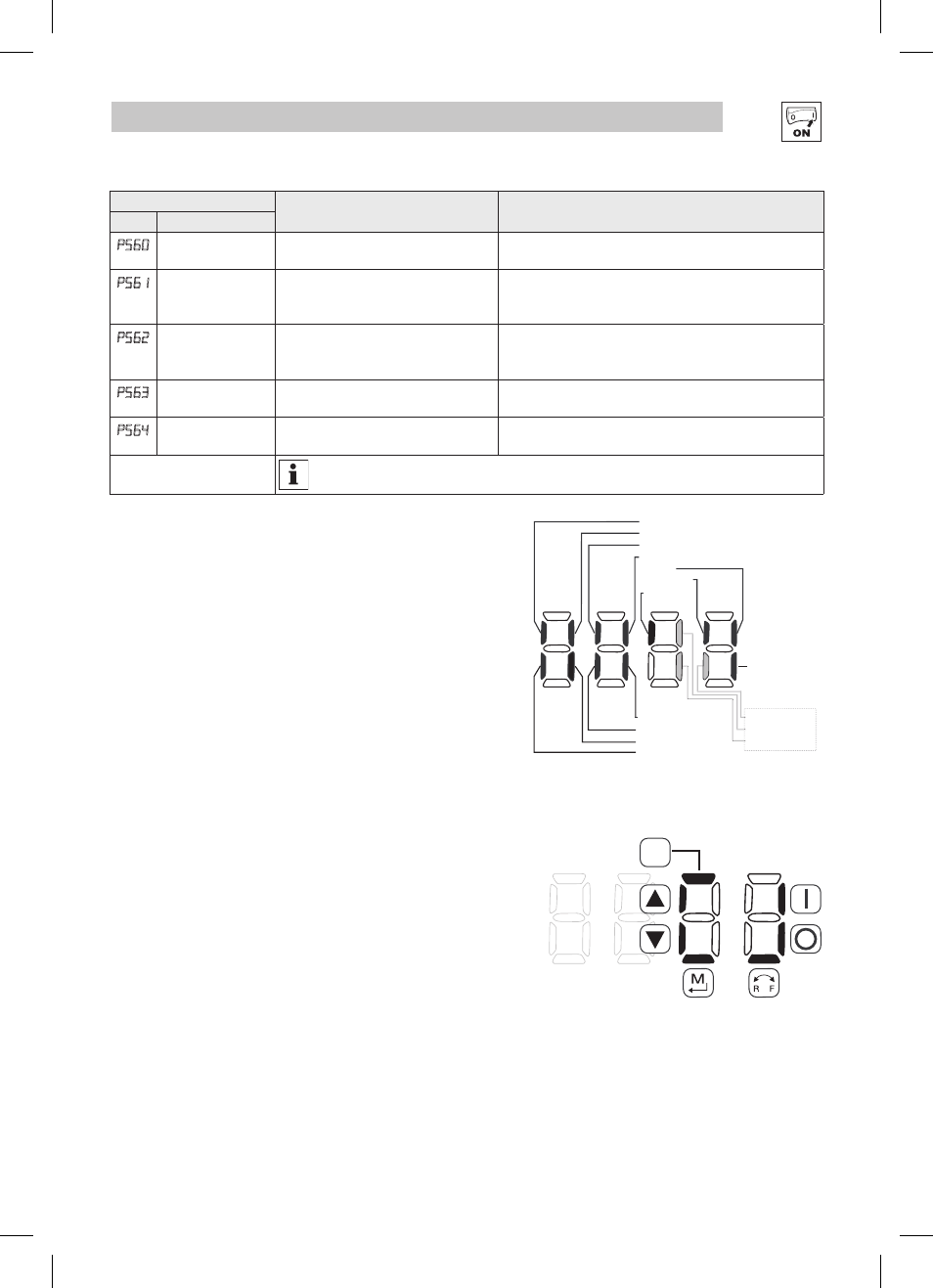
4.5.7.1 Terminal & Protection Status Display
Parameter P530 allows monitoring of the control terminal
points and common drive conditions:
An illuminated LED segment indicates:
• the protective circuit is active (LED 1)
• the Logic Assertion Switch is set to High (+)
• input terminal is asserted (LED 2)
• output terminal is energized (LED 4)
• the Charge Relay is not a terminal, this segment will
be illuminated when the Charge Relay is energized
(LED 4).
4.5.7.2 Keypad Status Display
Parameter P531 allows monitoring of the keypad
pushbuttons:
An illuminated LED segment indicates when the button is
depressed.
LED 1 and LED 2 are used to indicate pushbutton presses on
a remote keypad that is attached to the drive. LED 3 and LED
4 indicate button presses on the local drive keypad.
Input 13C
Input 13A
Factory Reserved
Protective Diagnostic
Current Limit Diagnostic
Logic Assertion Switch
Input 1
Input 13B
Relay
Output 14
Input 13D*
* Input 13D available on 15-60HP (11-45kW) models only
LED #
1
2
3
4
Charge
Relay
Auxiliary Relay
Input 13F
Input 13E
Additional I/O Module only
CTRL