Commissioning – Lenze ESV SMV frequency inverter User Manual
Page 36
34
Lenze SMVector 13465100 EDBSV01 EN v18
Commissioning
Code
Possible Settings
IMPORTANT
No.
Name
Default Selection
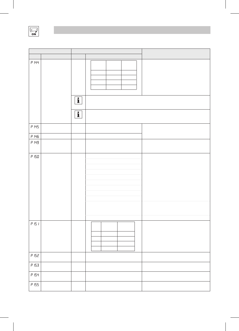
P144
Digital Output
Inversion
P144
Invert
P142
Invert
P140
0
NO
NO
1
NO
YES
2
YES
NO
3
YES
YES
Used to invert the selections for P140 (Relay Output)
and P142 (TB-14 Output).
EXAMPLE: When P140 = 6 (AT SPEED), the relay is
energized when output frequency = commanded
frequency. IF P144=1 or 3, then P140 is inverted
(INVERSE AT SPEED) and the relay is energized
when the output frequency does
not equal the
command frequency.
NOTE
Inverting P140 or P142 when the parameter is set to NONE (0) will result in the output being
energized continuously.
NOTE
For SMVector drives rated at 0.33 to 10 HP (0.25 to 7.5 kW), P144 is only available with
software versions 3.0 and higher (refer to P501).
p145
Loss of Load
Threshold
0
0
{%} 200
P140, P142 = 10: Output will energize if motor
load falls below the P145 value longer than the
P146 time
p146
Loss of Load Delay
0.0
0.0 {s} 240.0
p149
Analog Output Offset
0.0
0
{%} 100
Scaled value. Example: P149 = 10%, Scaled
variable = freq, P150 = 1, P152 = 60Hz; then
TB30 = 0VDC below 6Hz
p150
TB-30 Output
0
0 None
2-10 VDC signal can be converted to 4-20 mA with
a total circuit impedance of 500
W
1 0-10 VDC Output Frequency
2 2-10 VDC Output Frequency
3 0-10 VDC Load
4 2-10 VDC Load
5 0-10 VDC Torque
6 2-10 VDC Torque
7 0-10 VDC Power (kW)
8 2-10 VDC Power (kW)
9 Network Controlled
SMV models < 15HP (11kW) require an optional
communication module (refer to the network
module documentation).
10 Sequencer Controlled
Value set in individual sequencer segments
p151
Add Analog Input to
TB-30 Output
0
P151
Add TB-25
(4-20mA)
Add TB-5
(0-10VDC)
0
NO
NO
1
NO
YES
2
YES
NO
3
YES
YES
This parameter adds the analog input signal(s) to
the TB-30 Output signal. EXAMPLE: If a drive is
running at 60Hz with P150 set to 1 (0-10VDC Freq)
and P152 set to 240.0Hz, the output at TB-30 would
be 2.5VDC. If there is a 2.0VDC signal going into
TB-5 and P151 is set to 1 (ADD TB-5), the output
at TB-30 would become 4.5VDC.
p152
TB-30 Scaling:
Frequency
60.0
3.0
{Hz} 2000
If P150 = 1 or 2, sets the frequency at which output
equals 10 VDC
p153
TB-30 Scaling: Load
200
10
{%} 500
If P150 = 3 or 4, sets the Load (as a percent of
drive current rating) at which output equals 10 VDC.
p154
TB-30 Scaling:
Torque
100
10
{%} 1000
If P150 = 5 or 6, sets the Torque (as a percent of
motor rated torque) at which output equals 10 VDC
p155
TB-30 Scaling:
Power (kW)
1.0
0.1
{kW} 200.0
If P150 = 7 or 8, sets the power at which output
equals 10 VDC