Commissioning – Lenze ESV SMV frequency inverter User Manual
Page 52
50
Lenze SMVector 13465100 EDBSV01 EN v18
Commissioning
Code
Possible Settings
IMPORTANT
No.
Name
Default Selection
Segment #6
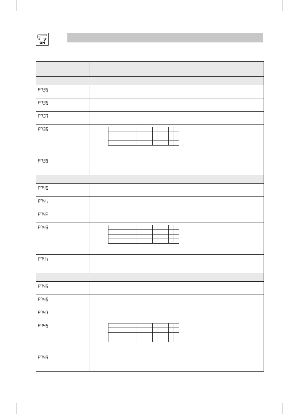
P735
Segment #6
Frequency Setpoint
0.0
-500.0 {Hz} 500.0
If P112 = 1, negative sign forces reverse
direction
P736
Segment #6
Accel/Decel Time
20.0
0.0
{sec} 3600.0
P737
Segment #6
Time in current step
0.0
0
0.0
{P708} 6553.5
0
{P708} 65535
Scaling/units depend on P708
Skip segment if time = 0
P738
Segment #6
Digital Output State
0
Value set in P738
0 1 2 3 4 5 6 7
Relay (Bit 0)
0 1 0 1 0 1 0 1
TB14 (Bit 1)
0 0 1 1 0 0 1 1
I/O option Relay (Bit 2)
0 0 0 0 1 1 1 1
NOTE: P441 is the Relay Output (TB-19, 20, 21) of the
optional Digital I/O module (ESVZAL0, ESVZAL1).
bit = 0: OFF (De-energized)
bit = 1: ON (Energized)
The corresponding digital output/relay must be
set to accept data from the sequencer: P140,
P142, P441 = 27
P739
Segment #6 TB30
Analog Output
Value
0.00
0.00
{VDC} 10.00
TB30 configuration parameter must be set to
accept this value: P150 = 10
Segment #7
P740
Segment #7
Frequency Setpoint
0.0
-500.0 {Hz} 500.0
If P112 = 1, negative sign forces reverse
direction
P741
Segment #7
Accel/Decel Time
20.0
0.0
{sec} 3600.0
P742
Segment #7
Time in current step
0.0
0
0.0
{P708} 6553.5
0
{P708} 65535
Scaling/units depend on P708
Skip segment if time = 0
P743
Segment #7
Digital Output State
0
Value set in P743
0 1 2 3 4 5 6 7
Relay (Bit 0)
0 1 0 1 0 1 0 1
TB14 (Bit 1)
0 0 1 1 0 0 1 1
I/O option Relay (Bit 2)
0 0 0 0 1 1 1 1
NOTE: P441 is the Relay Output (TB-19, 20, 21) of the
optional Digital I/O module (ESVZAL0, ESVZAL1).
bit = 0: OFF (De-energized)
bit = 1: ON (Energized)
The corresponding digital output/relay must be
set to accept data from the sequencer: P140,
P142, P441 = 27
P744
Segment #7 TB30
Analog Output
Value
0.00
0.00
{VDC} 10.00
TB30 configuration parameter must be set to
accept this value: P150 = 10
Segment #8
P745
Segment #8
Frequency Setpoint
0.0
-500.0 {Hz} 500.0
If P112 = 1, negative sign forces reverse
direction
P746
Segment #8
Accel/Decel Time
20.0
0.0
{sec} 3600.0
P747
Segment #8
Time in current step
0.0
0
0.0
{P708} 6553.5
0
{P708} 65535
Scaling/units depend on P708
Skip segment if time = 0
P748
Segment #8
Digital Output State
0
Value set in P748
0 1 2 3 4 5 6 7
Relay (Bit 0)
0 1 0 1 0 1 0 1
TB14 (Bit 1)
0 0 1 1 0 0 1 1
I/O option Relay (Bit 2)
0 0 0 0 1 1 1 1
NOTE: P441 is the Relay Output (TB-19, 20, 21) of the
optional Digital I/O module (ESVZAL0, ESVZAL1).
bit = 0: OFF (De-energized)
bit = 1: ON (Energized)
The corresponding digital output/relay must be
set to accept data from the sequencer: P140,
P142, P441 = 27
P749
Segment #8 TB30
Analog Output
Value
0.00
0.00
{VDC} 10.00
TB30 configuration parameter must be set to
accept this value: P150 = 10