Commissioning, 3 advanced setup parameters – Lenze ESV SMV frequency inverter User Manual
Page 37
Lenze SMVector 13465100 EDBSV01 EN v18
35
Commissioning
4.5.3
Advanced Setup Parameters
Code
Possible Settings
IMPORTANT
No.
Name
Default Selection
p156
Analog Inputs
Configuration
0
0 TB5: (0-10 VDC); TB25: (4-20mA)
1 TB5: (0 - 5 VDC); TB25: (4-20mA)
2 TB5: (2 - 10 VDC); TB25: (4-20mA)
4 TB5: (0-10 VDC); TB25: (0-20mA)
5 TB5: (0 - 5 VDC); TB25: (0-20mA)
6 TB5: (2 - 10 VDC); TB25: (0-20mA)
p157
TB5 (0-10V) Analog
Input Monitoring
Action
0
0 No Action
Selects the reaction to a loss of the 0-10V signal
at TB5
500ms is the minimum time above/below
Monitoring Level (P158) before triggering the
drive to trip or run at a preset speed.
For P157 = 3 or 6, the accel/decel time is set
in P786.
NOTE: P157 has priority over P163 and TB-13
presets/auto references (P121-P124)
1 If TB5 < P158 - Trip Fault F.FAU
2 If TB5 < P158 - Run Preset #8
3 If TB5 < P158 - Run Preset Seg. #16
4 If TB5 > P158 - Trip Fault F.FAU
5 If TB5 > P158 - Run Preset #8
6 If TB5 > P158 - Run Preset Seg. #16
p158
TB5 (0-10V) Analog
Input Monitoring
Level (ML)
0.0
-10.0 {VDC} 10.0
Negative input voltage is not currently supported.
p159
0-10V Analog Input
Deadband
0.0
0
{VDC} 10.0
Not active if [-10 to +10 VDC] option is selected.
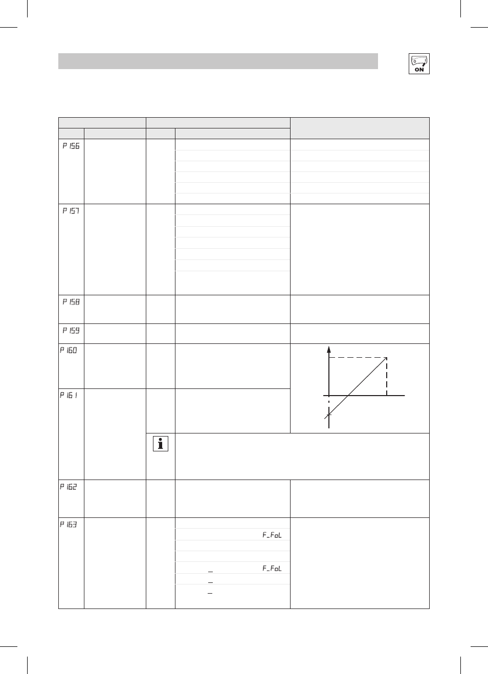
P160
Speed at Minimum
Signal
0.0
-999.0 {Hz} 1000
f
P161
P160
ref
10V
(20mA)
0V
(4mA)
V0111
P161
Speed at Maximum
Signal
60.0
-999.0 {Hz} 1000
NOTE
• P160 sets the output frequency at 0% analog input
• P161 sets the output frequency at 100% analog input
• P160 or P161 < 0.0 Hz: For scaling purposes only; does not indicate opposite direction!
• P160 > P161: Drive will react inversely to analog input signal
p162
Analog Input Filter
0.01
0.00 {s} 10.00
• Adjusts the filter on the analog inputs (TB-5
and TB-25) to reduce the effect of signal noise
• The P162 delay time will affect the response
time of diagnostic parameters (P520-P523).
P163
TB-25 (4-20mA)
Analog Input
Monitoring Action
0
0 No Action
• Selects the reaction to a loss of the 4-20 mA
signal at TB-25.
• Signal is considered lost if it falls below the
value set in P164
• Digital outputs can also indicate a loss of 4-20
mA signal; see P140, P142
• For P163 = 3 or 6, the accel/decel time is
set in P781.
NOTE: P163 has priority over TB-13 presets/auto
references (P121-P124)
1 If TB25 < P164 - Trip Fault F.FoL
2 If TB25 < P164 - Run Preset #7
3 If TB25 < P164 - Run Preset Seg. #15
4 If TB25 > P164 - Trip Fault F.FoL
5 If TB25 > P164 - Run Preset #7
6 If TB25 > P164 - Run Preset Seg. #15