Multiserver 5000, Table 9-5. synchronous clocking – Black Box 5000 User Manual
Page 92
Multiserver 5000
90
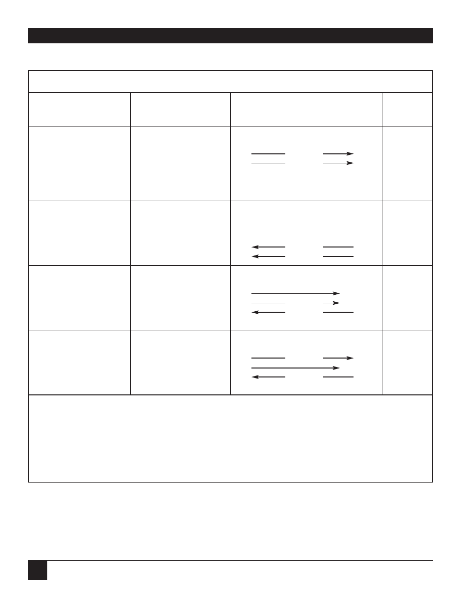
Table 9-5. Synchronous Clocking
Cable Part
Configuration
Description of Use
Cable Diagrams for Clocks
(1)
Number
Normal Synchronous
Use when DTE is
Multiserver
DTE
or Cascade
co-located with
Multiserver. 15
TX
Clock
15
EZ422
To DTE
TX and RX clocks
17
RX Clock
17
EDN16C
are supplied by
TX Clock Internal
the Multiserver.
RX Clock Internal
Normal Synchronous
Use when tail-circuit
Multiserver
DCE
synchronous modem
To DCE
or DCE is attached to
15 — not used
EZ423
Multiserver. DCE
17 — not used
EZ424
TX Clock External
supplies both clocks.
18
RX Clock
15
RX Clock External
24
TX Clock
17
Normal Synchronous
Use when attached
Multiserver
DCE/DTE
device is providing the
To DCE or DTE
TX clock and the
15
(2), (3)
Depends
Multiserver is providing
17
RX Clock
(2), (3)
upon
TX Clock External
the RX clock.
24
TX Clock
(2)
application.
RX Clock Internal
Special Synchronous
Use when attached
Multiserver
DCE/DTE
device is providing the
To DCE or DTE
clock for RX data and
15
TX Clock
(2)
Depends
the Multiserver is
17
(2), (3)
upon
TX Clock Internal
providing the TX clock.
18
RX Clock
(2)
application.
RX Clock External
(1) TX clock and RX clock are used to indicate on which line the Multiserver supplies or accepts the transmit and
receive clock signals. The TX and RX clocks are always named respective to the Multiserver port.
(2) Pin assignments depend on attached device.
(3) Multiserver will output the clock.
(4) Specifications of crossover cable depend upon attached device.