Chapter 9: data-channel configuration – Black Box 5000 User Manual
Page 87
CHAPTER 9: Data-Channel Configuration
85
performed after changing the port configuration to
sync. Leave the menu and perform the reset, and try
this procedure again.
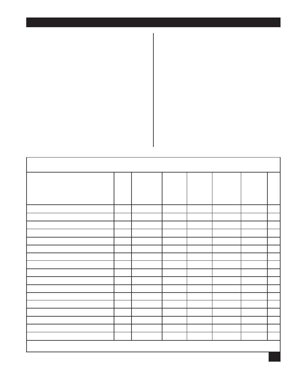
The CHANNEL CHARACTERISTICS menu will
appear. This menu differs depending on the sync
protocol selected during port configuration. Table
9-2
, below, lists each sync protocol and their
channel characteristic options. The numbers in the
Table 9-2
correspond to the menu option for that
particular protocol. For example, the third item on
the CHANNEL CHARACTERISTICS menu for
ASCII Bisync is Maximum Transmit Block Size; for
Fast Packet it is DSR Control.
Table 9-3, Sync Channel Characteristics
, describes
each of the sync channel characteristics and gives
default values used for each of the sync protocols.
Three of the sync channel characteristics—data
Table 9-2. Sync Channel Characteristics Used for Each Sync Protocol
ASCII Bisync
EBCDIC Bisync
H-P Sync
DLC
RTS/CTS
Sync-Pad MICOM DLC MICOM Voice Fast Packet TDM
Data Rate
1
1
1
1
1
1
1
Channel Clocking
2
2
2
2
2
2
Maximum Transmit Block Size
3
3
3
3
Maximum Receive Block Size
4
4
4
4
Interface Type
5
5
5
3
5
3
Carrier Mode
6
6
6
4
6
Sync Character
7
7, 8*
2
4
Number of Leading Syncs
8
9
Pad Character
9
10
Number of Leading Pad Characters
10
11
Number of Trailing Pad Characters
11
12
Buffer Control
9
12
13
5
7
Encoding
7
Idle Fill
8
Clock Flow Control
10
13
14
6
8
DSR Control
11
14
15
7
9
3
5
Priority
12
15
16
8
10
4
*Option 7 is Sync Character 1; Option 8 is Sync Character 2.
rate, channel clocking, and interface type—
reference other tables in this chapter. These tables
are located immediately after Table 9-3.
C
ONTROL
S
IGNALS
A synchronous channel supports four control-signal
pairs necessary to support both direct-connected
and modem applications: DTR/DSR, BO/RI,
RTS/CD and Pin 11/CTS. The first two pairs
(DTR/DSR and BO/RI) are passed end-to-end in
the Multiserver network, and their levels are set by
the attached devices. The last two (RTS/CD and Pin
11/CTS) are interpreted and generated locally by
the Multiserver. The particular operation of these
signals depends upon the protocol selected, the
interface type, and the carrier mode configured by
the operator.