Module installation, Multiserver 5000, 1 module stacking order – Black Box 5000 User Manual
Page 42: Module, Isu voice/fax 12-channel cem 6-channel cem ccm nms
Multiserver 5000
40
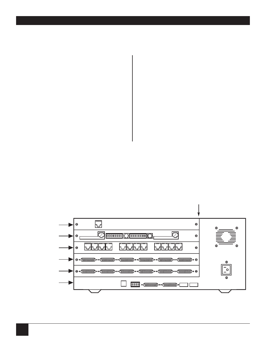
5.1 Module Stacking Order
Although you are not actually installing the
modules yet, it is important to become familiar with
the five chassis positions available for modules in
the Multiserver unit. These are identified from
bottom to top as module locations A through E (see
Figure 5-1
). The possible hardware-configuration
combinations are numerous. Regardless of the
combination you choose, the Communications
Control Module (CCM) must always be in module
location A. The optional NMS module is always
installed directly below the CCM. The rest of the
modules should be installed in the following order,
from bottom to top:
• 6-channel CEM
• 12-channel CEM
• Voice/fax module
• RLB module
• 56K CSU/DSU module
Stacking is done from bottom to top without
skipping a module location. For example, if you
have three modules (a CCM and two optional
modules), the modules should be stacked in
module locations A through C with locations D
and E left open. If there are four modules, module
location E will be left unused.
5. Module Installation
12345678
12345678
S1
S2
1
2
4
5
6
ALARM
G C NONC
115/230
VAC
1
2
3
4
5
6
7
8
9
10
11
12
12
A
B
C
D
E
3
1
2
4
5
6
DDS SERVICE
LINE 1
KTS
OPX
SB M E SG R1 T1 R
T
VOICE CHANNEL 1
LOG PORT
COMMAND
12345678
12345678
MODEM
ISU
VOICE/FAX
12-CHANNEL CEM
6-CHANNEL CEM
CCM
NMS
MODULE
KTS
OPX
SB M E SG R1 T1 R
T
VOICE CHANNEL 2
3
Figure 5-1. A letter on the right side of the module indicates location.
LETTERS THAT INDICATE
MODULE LOCATION