Multiserver 5000 – Black Box 5000 User Manual
Page 174
Multiserver 5000
172
This menu offers the following test options:
Option
Description
Sync
Causes a sync port to be placed in
Channel
local echo loopback similar to the
Loopback
async echo.
WARNING
: This test will interrupt
all channels connected across the
link.
Remote
Sets up the unit to expect its own
Composite
databack. This function is required
Loopback
for tests intiated by external
communication devices (modem or
CSU/DSU) or telco.
WARNING
: This test will interrupt
all channels connected across the
link.
LED Test
Lights all of the indicator lights
(LEDs) on all modules for five
seconds.
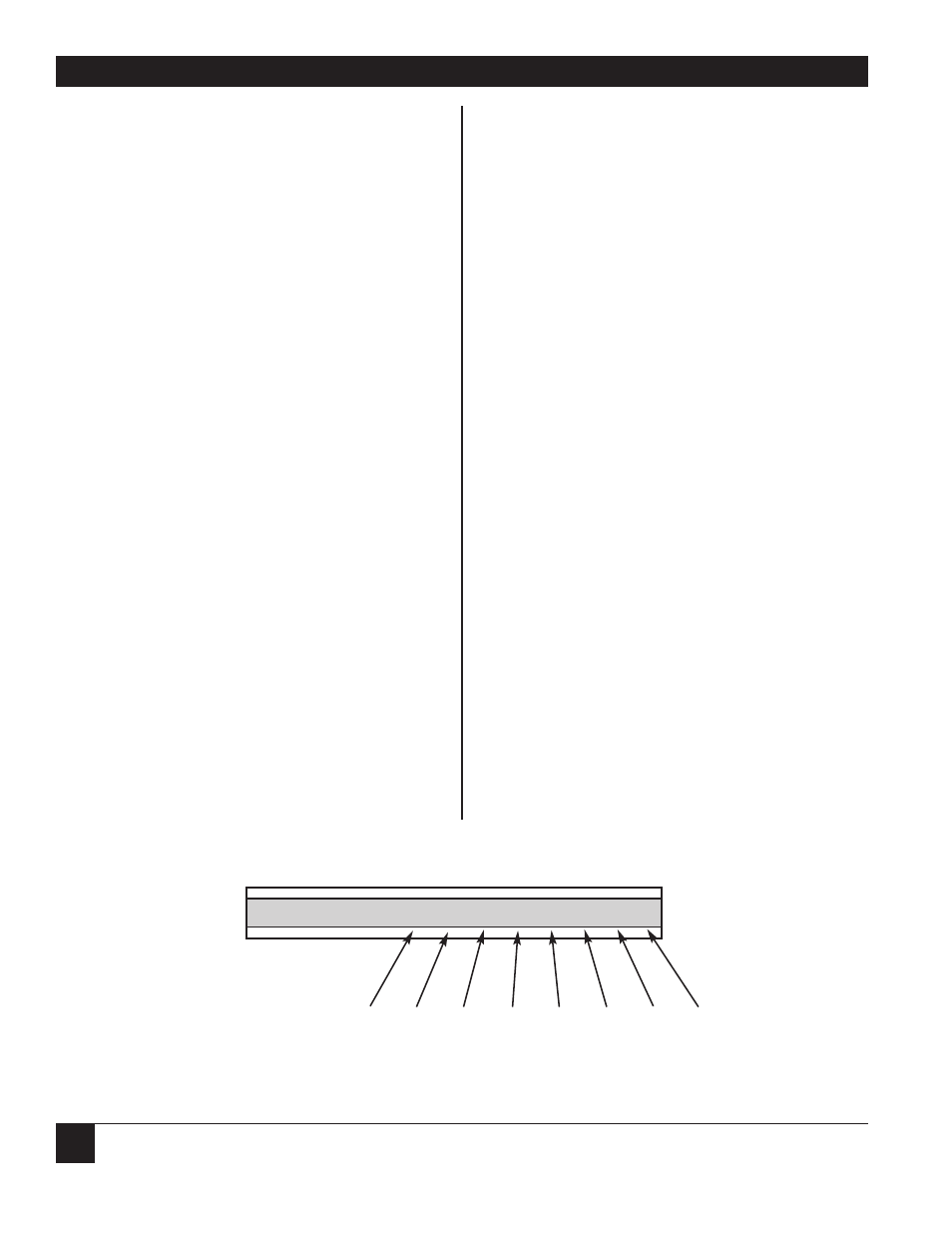
Monitor Ch.
CCM indicator lights display the
Interface
status of the interface signals. See
Signals
Figure 13.4.
Terminate
Terminates all tests initiated at this
Test
menu (except LED Test, which
automatically terminates).
Once a test is initiated, an [Active] message is
displayed on the LCD. All tests (except the LED
Test) remain active until terminated with Terminate
Test. The next time you cycle through the LCD
Menus, an [Active] message is displayed,
meaning the test was previously invoked and is still
active. When a test is complete or is terminated, the
LCD will display [Inactive].
V
OICE
/F
AX
When this menu is selected, the screen will prompt
for the channel number to be tested. If a voice/fax
module is installed in the Multiserver, the following
diagnostic options will be offerred:
Option
Description
Self-Test
Verifies that the memory and analog
circuit of the voice/fax channel is
working properly. When this test is
initiated, the display will read
[Started]
. Press the EXEcute key
again to ascertain the status of the
test (Passing/Failing).
Local Loop
Causes the voice/fax channel to
compress the local speech signal,
and then passes this signal through
the reconstruction process back to
the local receiver. It sets the
voice/fax channel to the off-hook
condition during the test. When this
test is initiated, the display will read
[Active]
.
Input Level
Monitors the level of the incoming
A6 A5 A4 A3 A2 A1
AT BO
Figure 13.4 “Monitor Channel Interface Signals” Test.
Pin 11*
*Not used on links.
CD
DSR
RI
CTS
RTS
DTR
Busy*